Ceiling fan motor housing and cover side fixing structure

Active Publication Date: 2017-06-22
CHAMP RAY INDAL
View PDF5 Cites 5 Cited by
  • Summary
  • Abstract
  • Description
  • Claims
  • Application Information

AI Technical Summary

Benefits of technology

[0004]In view of the aforementioned problems of the conventional ceiling fan motor, it is a primary objective of the present invention to overcome the aforementioned problems such as increasing the widt

Problems solved by technology

However, the overall structure includes many components and thus causes an inconvenient assembling process, and a flange is extended outwardly from edges

Method used


Image

  • Ceiling fan motor housing and cover side fixing structure
  • Ceiling fan motor housing and cover side fixing structure
  • Ceiling fan motor housing and cover side fixing structure

Examples


Embodiment Construction

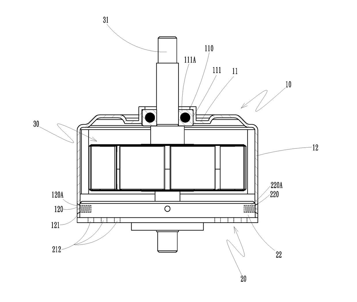
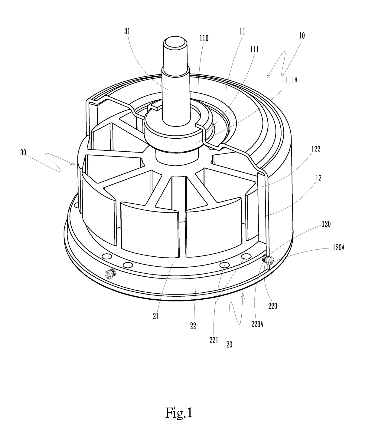
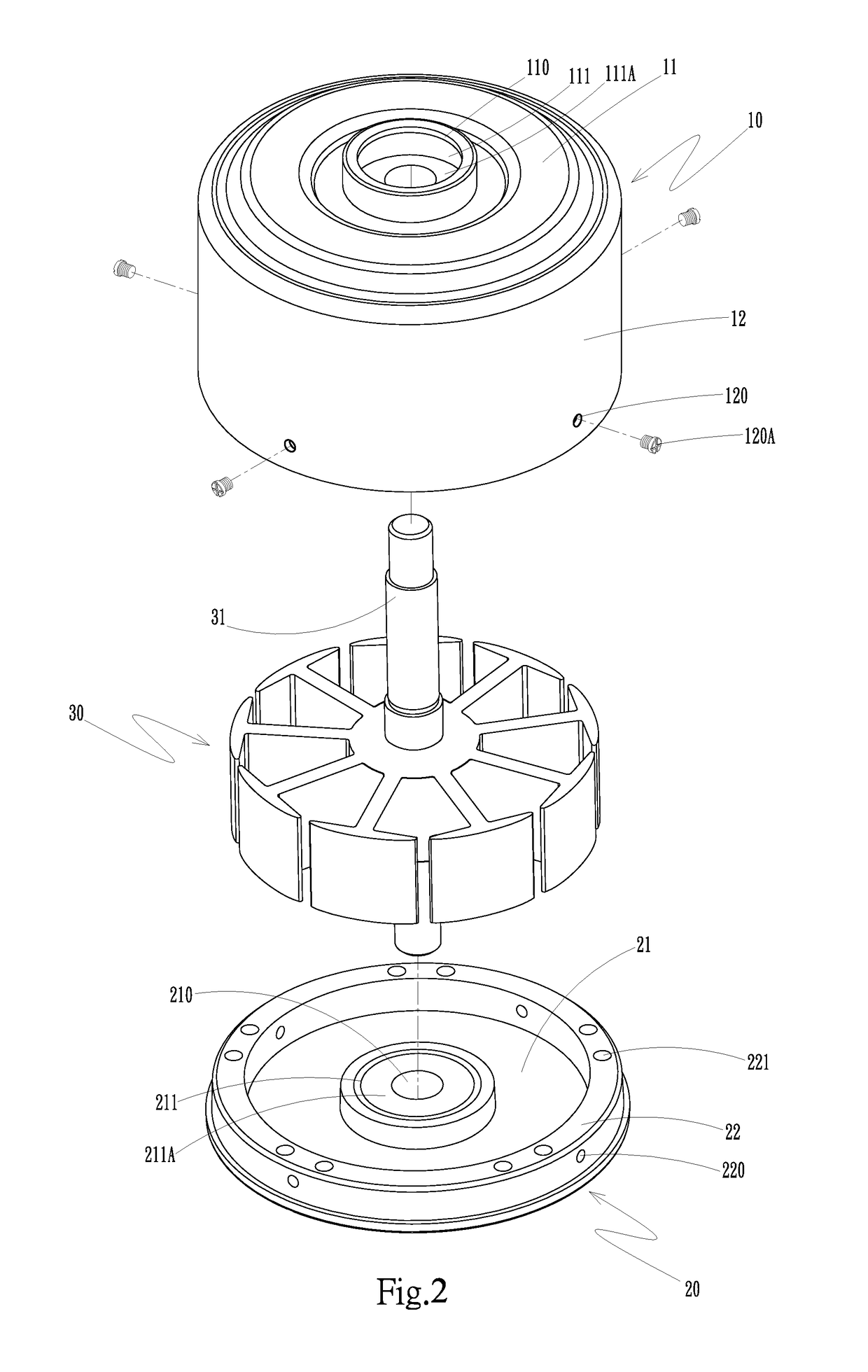
[0014]With reference to FIGS. 1 to 3 for a partial cross-sectional view, an exploded view and a side cross-sectional view of a ceiling fan motor housing and cover side fixing structure in accordance with the present invention respectively, the structure comprises the following components.

[0015]A motor housing 10 has a top side 11 and a sidewall 12, and an upper through hole 110 is formed at the center of the top side 11, and an upper accommodating groove 111 is formed and configured to be opposite to the upper through hole 110, and the upper accommodating groove 111 includes a bearing 111A accommodated and installed therein, and a plurality of side guide holes 120 are formed and configured to be opposite to the sidewall 12, and a passing-through fixing member 120A is passed and installed into each respective side guide hole 120, wherein the passing-through fixing member 120A is a bold, and a rotor 122 is installed around an inner side of the sidewall 12.

[0016]A cover 20 has a cover ...


PUM


Abstract

A ceiling fan motor housing and cover side fixing structure includes a motor housing, a cover and a stator. The motor housing includes a rotor and plural side guide holes formed on a sidewall. The cover includes plural fixing holes formed at an edge of a top circular flange, and the side guide holes opposite to the fixing holes are fixed by plural passing-through fixing members, so that the motor housing and the cover are combined for accommodating the stator to simplify the overall assembly of the ceiling fan motor effectively, and provide a convenient way of combining the motor housing and the cover without increasing the width. Further, the wire winding space of the stator in the motor housing and the cover of the ceiling fan motor is increased for convenient assembling.

Description

[0001]The current application claims a foreign priority to application number 104142958 filed on Dec. 21, 2015 in Taiwan.FIELD OF THE INVENTION[0002]The present invention relates to a ceiling fan motor housing and cover side fixing structure, and more particularly to a fixing of laterally fixing a motor housing and a cover to increase the wire winding space of a rotor.BACKGROUND OF THE INVENTION[0003]With reference to FIG. 6 for a conventional ceiling fan motor, the conventional ceiling fan motor 40 comprises an upper casing 41, a middle ring 42, a lower casing 43 and a stator 44, and the upper casing 41 and the lower casing 43 are engaged with upper and lower sides of the middle ring 42 respectively, and a plurality of screws 45 are passed and combined between the upper casing 41 and the lower casing 43, and after the upper casing 41, the middle ring 42 and the lower casing 43 are combined, an accommodating space is formed for accommodating a stator 44, and a rotor 420 is installed...

Claims


Application Information

Patent Timeline
IPC IPC(8): F04D29/64H02K5/20F04D25/08
CPCF04D29/646H02K5/20F04D25/088F04D25/0606H02K1/2786H02K7/14H02K5/207
Inventor YANG, WEI-CHENG
Owner CHAMP RAY INDAL
Why Eureka
Try Eureka