Light source module and lamp using the same

a technology of light source module and lamp, which is applied in the direction of semiconductor lasers, fixed installations, lighting and heating apparatus, etc., can solve the problems of electrification failure occurring between the lead terminal and the circuit pattern of the circuit board, and achieve the effect of reducing the occurrence of electrification failure between the pin terminal and the electrically conductive member and further reducing the occurrence of electrification failur

Active Publication Date: 2017-06-22
KOITO MFG CO LTD
View PDF3 Cites 1 Cited by
  • Summary
  • Abstract
  • Description
  • Claims
  • Application Information

AI Technical Summary

Benefits of technology

[0021]According to such a configuration, the pin terminal falling out of the power supply member as a result of the force generated at the pin terminal that pulls in the longitudinal direction of the pin terminal is suppressed. Accordingly, occurrences of electrification failure between the pin terminal and the electrically conductive member can be further reduced.
[0022]A light source module according to one or more embodiments of the present invention may reduce electrification failures. According to one or more embodiments of the present invention, a lamp employs a light source module according to one or more embodiments of the present invention.

Problems solved by technology

In cases where this pulling force acts on the lead terminals, there is a concern for electrification failure occurring between the lead terminals and the circuit pattern of the circuit board.

Method used


Image

  • Light source module and lamp using the same
  • Light source module and lamp using the same
  • Light source module and lamp using the same

Examples


modified examples

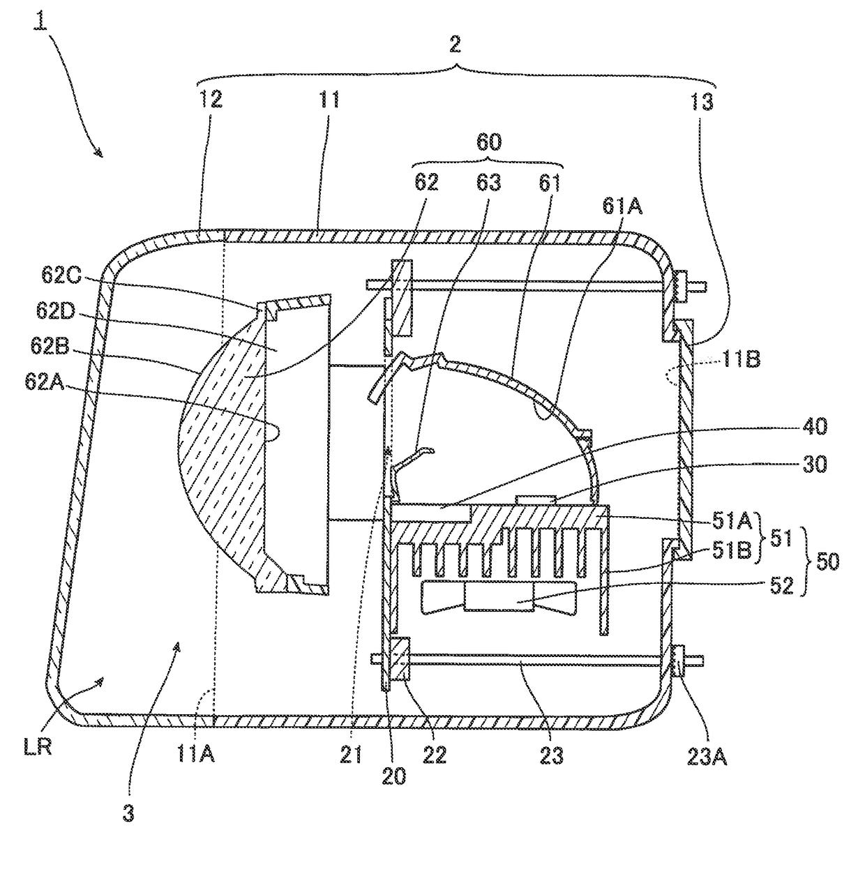
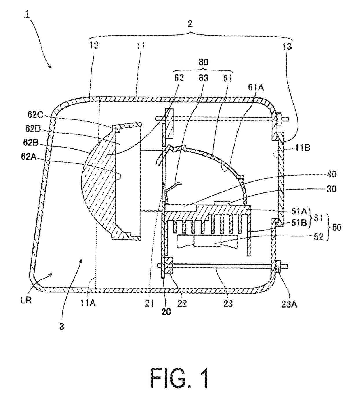
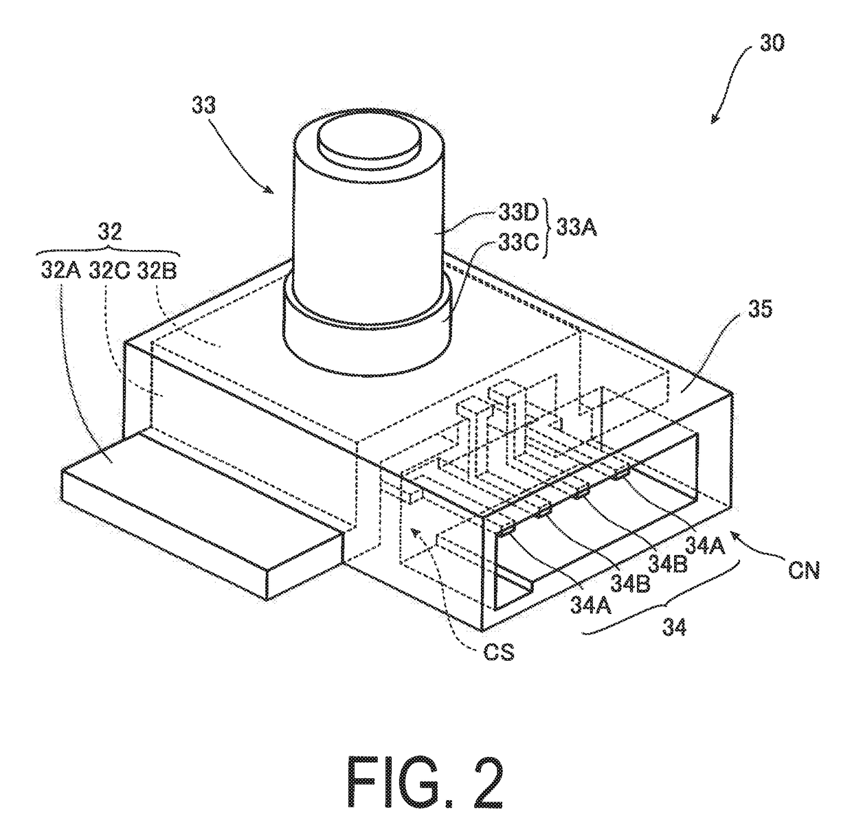
[0073]In one or more the embodiments described above, a portion of the heat radiating member 32 is covered by the covering material 35. However, provided that the covering material 35 does not cover at least the connection portions of the pin terminals 33B with the bus bars 34A, the entire heat radiating member 32 may be covered.

[0074]In one or more of the embodiments described above, the pin terminal bus bars 34A are disposed in a direction orthogonal to the longitudinal direction of the pin terminals 33B, from the first ends to the leading ends thereof. However, the pin terminal bus bars 34A need not be disposed in the direction orthogonal to the longitudinal direction of the pin terminals 33B. Regardless, in order for the pin terminal bus bars 34A to flex in the longitudinal direction of the pin terminals 33B and absorb the force generated in the pin terminals 33B as illustrated in FIG. 5, according to one or more embodiments of the present invention, the pin terminal bus bars 34...


PUM


Abstract

A light source module has a heat radiating member that has heat radiating properties and has a through-hole penetrating therethrough, a heat generating component having a heat generating component main body disposed on a side of a first opening of the through-hole, and a pin terminal connected to the heat generating component main body and inserted through the through-hole, an electrically conductive member disposed on a side of a second opening of the through-hole and connected to the pin terminal protruding from the second opening, and a covering material that covers and fixes at least a portion of the electrically conductive member and the heat radiating member. A connection portion of the electrically conductive member with the pin terminal is not covered by the covering material.

Description

BACKGROUND[0001]Technical Field[0002]The present invention relates to a light source module and a lamp using the same.[0003]Related Art[0004]Lamps are known in which a light source module is used that has a structure including, for example, a light emitting component, namely a semiconductor laser package, disposed on an interconnection substrate, and a heat radiating member made from metal interposed therebetween (see Patent Literature 1 below).[0005]The semiconductor laser package described in Patent Literature 1 below includes a base, namely a stem. The stem is pressed into and fixed to a hole in a heat sink, which is made from metal and is disposed on one face of a circuit board. A laser element is mounted on the stem and a tubular cap is provided on the stem so as to surround the laser element. Rod-like lead terminals are connected to the laser element, and the lead terminals are inserted into holes penetrating the interconnection substrate in a thickness direction and fixed to ...

Claims


Application Information

Patent Timeline
Patent Type & Authority Applications(United States)
IPC IPC(8): F21S8/10
CPCF21S48/328F21S48/125F21S48/1317F21Y2115/30F21S48/17F21S48/1225F21S48/1145H01S5/02476H01S5/023H01S5/0233H01S5/0235F21S41/16F21S41/176F21S41/192F21S41/255F21S41/333F21S41/43F21S45/435
Inventor SUZUKI, TETSUYAONODA, YUKIHIRO
Owner KOITO MFG CO LTD
Why Eureka
Try Eureka