
Hot water apparatus

a technology of hot water and apparatus, which is applied in the direction of lighting and heating apparatus, combustion types, burner ignition devices, etc., can solve problems such as insulation failure between the two electrodes, and achieve the effect of suppressing the occurrence of insulation failur

Inactive Publication Date: 2018-05-03
NORITZ CORP
View PDF26 Cites 6 Cited by
  • Summary
  • Abstract
  • Description
  • Claims
  • Application Information

AI Technical Summary

Benefits of technology

The present invention is related to a hot water apparatus that reduces insulation failure between two electrodes. The invention includes a groove portion on the tip end surface of the apparatus, which decreases in width towards the base end portion and is recessed from the top end surface towards the base end portion. This design allows condensate generated on the wall surface to flow through the groove portion, reducing the likelihood of connection between the two electrodes via condensate and resulting conduction between the electrodes. This design also prevents insulation failure between the two electrodes and improves the overall performance of the hot water apparatus.

Problems solved by technology

The condensate renders the two electrodes conducting to each other and insulation failure between the two electrodes is disadvantageously caused.

Method used


Image

  • Hot water apparatus
  • Hot water apparatus
  • Hot water apparatus

Examples


case 11

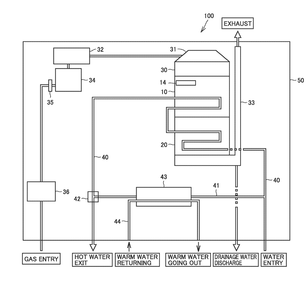
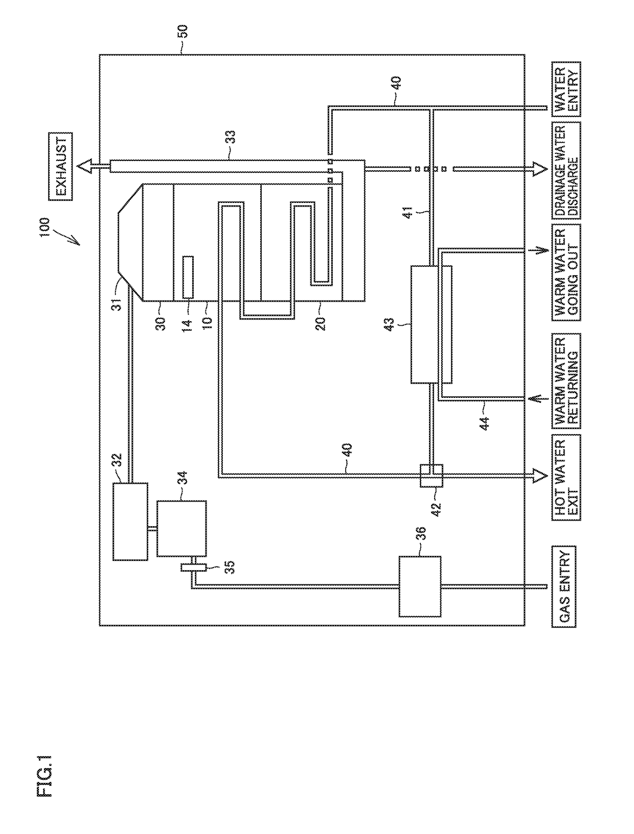
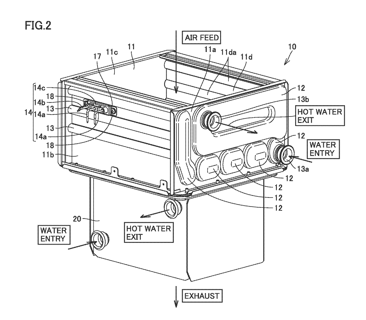
[0055]Case 11 includes a first sidewall 11a, a second sidewall 11b, a third sidewall 11c, and a fourth sidewall 11d. First sidewall 11a to fourth sidewall 11d are connected to form a quadrangular frame.

[0056]First sidewall 11a and third sidewall 11c face each other. Second sidewall 11b and fourth sidewall 11d face each other. Each of first sidewall 11a to fourth sidewall 11d has a wall surface serving as a partition between the inside and the outside of case 11.

[0057]Case 11 in a form of the frame opens upward and downward. The combustion gas can thus be supplied to the inside of case 11 through the upper opening of case 11. The combustion gas can be exhausted to the outside of case 11 through the lower opening of case 11.

[0058]Header 12 is provided on an outer surface of first sidewall 11a. A joint 13a on the water entry side and a joint 13b on the hot water exit side are attached to header 12 provided on the outer surface of first sidewall 11a. A not-shown header is provided also ...


PUM


Abstract

A hot water apparatus includes a burner, a sensible heat recovery heat exchanger, and an ignition plug. The sensible heat recovery heat exchanger includes a case. The ignition plug includes an insulator portion and two electrodes. The insulator portion includes a base end portion and a tip end portion. The tip end portion includes a tip end surface and a groove portion. The tip end surface is arranged opposite to the base end portion. The groove portion is recessed from the tip end surface toward the base end portion. The groove portion is arranged between the two electrodes and provided across top and bottom ends of the tip end portion. The groove portion has a lateral width decreasing from the top end toward the bottom end of the tip end portion.

Description

BACKGROUND OF THE INVENTIONField of the Invention[0001]The present invention relates to a hot water apparatus and particularly to a hot water apparatus including a burner and a heat exchanger.Description of the Background Art[0002]A hot water apparatus including an ignition plug having a plurality of electrodes is disclosed, for example, in Japanese Patent Laying-Open No. 7-190359. In the ignition plug of the hot water apparatus, the plurality of electrodes are held in a base portion (an insulator portion) at a distance from one another. The insulator portion is arranged in a side plate (a wall surface) of a case of a gas burner apparatus.[0003]In the ignition plug described in the publication, condensate generated on the wall surface of the case drops and adheres to the insulator portion. The condensate renders the two electrodes conducting to each other and insulation failure between the two electrodes is disadvantageously caused.SUMMARY OF THE INVENTION[0004]The present invention...

Claims


Application Information

Patent Timeline
Patent Type & Authority Applications(United States)
IPC IPC(8): F24H1/16F24H8/00F23D14/34F28D7/00F28F1/32
CPCF24H1/165F24H8/006F23D14/34F28D7/0075F28F1/325F28D21/0007F23N2035/24F28F9/0229F28D1/0417F28F1/02F28D2021/0024Y02B30/00F23N2235/24F23Q3/008F23D2207/00
Inventor WADA, NORIHIDE
Owner NORITZ CORP
Learn More