Method for measuring electrical isolation of a vehicle chassis

a technology of electrical isolation and vehicle chassis, which is applied in the direction of preventing measurement, dielectric strength testing, instruments, etc., can solve the problems of large errors in any one measurement, potential electrocution hazards, and further reducing the performance and response time of saej1766 prior art measurement systems

Active Publication Date: 2017-06-22
FARADAY&FUTURE INC
View PDF4 Cites 7 Cited by
  • Summary
  • Abstract
  • Description
  • Claims
  • Application Information

AI Technical Summary

Benefits of technology

[0011]In one aspect, the invention relates to a method of determining the isolation resistance between a chassis and a battery having a positive terminal and a negative terminal. In one embodiment, the method includes the steps of: measuring an open voltage (VP(open)) of the positive terminal; measuring an open voltage (VN(open)) of the negative terminal; closing switch S1 to connect resistor S1 between negative terminal and chassis; measuring a voltage (VN(S1 closed)) between the negative terminal and the chassis while switch S1 is closed; measuring a voltage (VP(S1 closed)) between positive terminal and chassis while switch S1 is closed; calculating the ratio (VP(S1 closed) / VN(S1 closed)) of the voltages VP(S1 closed) and VN(S1 closed);calculating the open ratio of the open voltages (VP(open) / VN(open));calculating the difference between the ratio (VP(S1 closed) / VN(S1 closed)) and the open ratio (VP(S2 open) / VN(S1 open)); and multiplying the value of the test resistor (R0) by the difference between the ratio (VP(S1 closed) / VN(S1 closed)) and the open ratio (VP(S2 open) / VN(S1 open)) to obtain the isolation resistance.
[0012]In another embodiment the voltage VN is measured across a test resistor. In yet another embodiment the test resistor is 4M Ohms to 10 M Ohms. In still yet another embodiment switch S1 is an optoisolated MOSFET switch. In still another embodiment the method further includes the step of isolating the battery if the isolation resistance is determined to be less that a specified value. In another embodiment the determination of isolation resistance is made while the battery is supplying power to a motor.
[0013]In another aspect, the invention relates to a method of determining an isolation resistance between a chassis and a battery, the battery having a positive terminal and a negative terminal. In another embodiment, the method includes the steps of: measuring an open voltage (VP(open)) of the positive terminal; measuring an open voltage (VN(open)) of the negative terminal; measuring a voltage (VP(S2 closed)) between the positive terminal and the chassis while switch S2 is closed; measuring a voltage (VN(S2 closed)) between the negative terminal and the chassis while switch S2 is closed; calculating the ratio (VN(S2 closed) / VP(S2 closed)) of the voltages VP(S2 closed) and VN(S2 closed); calculating the open ratio of the open voltages (VN(open) / VP(open)); calculating the difference between the ratio (VN(S2 closed) / VP(S2 closed)) and the open ratio (VN(open) / VP(open)); and multiplying the value of the test resistor (R0) by the difference between the ratio (VN(S2 closed) / VP(S2 closed)) and the open ratio (VN(open) / VP(open)) to obtain the isolation resistance.
[0014]In another embodiment the voltage VP is measured across a test resistor. In still another embodiment the test resistor is 4M Ohms to 10 M Ohms. In yet another embodiment switch S2 is an optoisolated MOSFET switch. In still yet another embodiment the method further includes the step of isolating the battery if the isolation resistance is determined to be less that a specified value. In another embodiment the determination of isolation resistance is made while the battery is supplying power to a motor.

Problems solved by technology

The isolation is designed to prevent an electrical shock hazard but can fail over time or due to a crash, which creates a potential electrocution hazard.
This is problematic if an isolation measurement is to be undertaken while the vehicle is being driven.
As a result, large errors may be introduced in any one measurement using the SAEJ1766 method.
In addition to the delay in measurement caused by the large time constant and the sensitivity to differential voltage fluctuations, the need to average multiple measurements further reduces the performance and response time of SAEJ1766 prior art measurement systems.
Although the prior art SAEJ1766 methods could avoid the averaging of measurements by restricting the measurements to periods when the propulsion system is not active, this would dramatically limit the usefulness of the prior art approach.

Method used


Image

  • Method for measuring electrical isolation of a vehicle chassis
  • Method for measuring electrical isolation of a vehicle chassis
  • Method for measuring electrical isolation of a vehicle chassis

Examples


Embodiment Construction

[0020]The method of the invention eliminates the sensitivity of the measurement of the isolation resistance calculation to differential high voltage changes occurring in the circuit during measurement. As a result, a very accurate isolation resistance measurement can be obtained even while battery voltage is widely varying during the test period. This allows for a more accurate assessment of the quality of the electrical insulation, while providing significantly faster evaluation time. The significantly improved resistance estimation allows for less averaging and filtering resulting in quicker detection of isolation resistance failures.

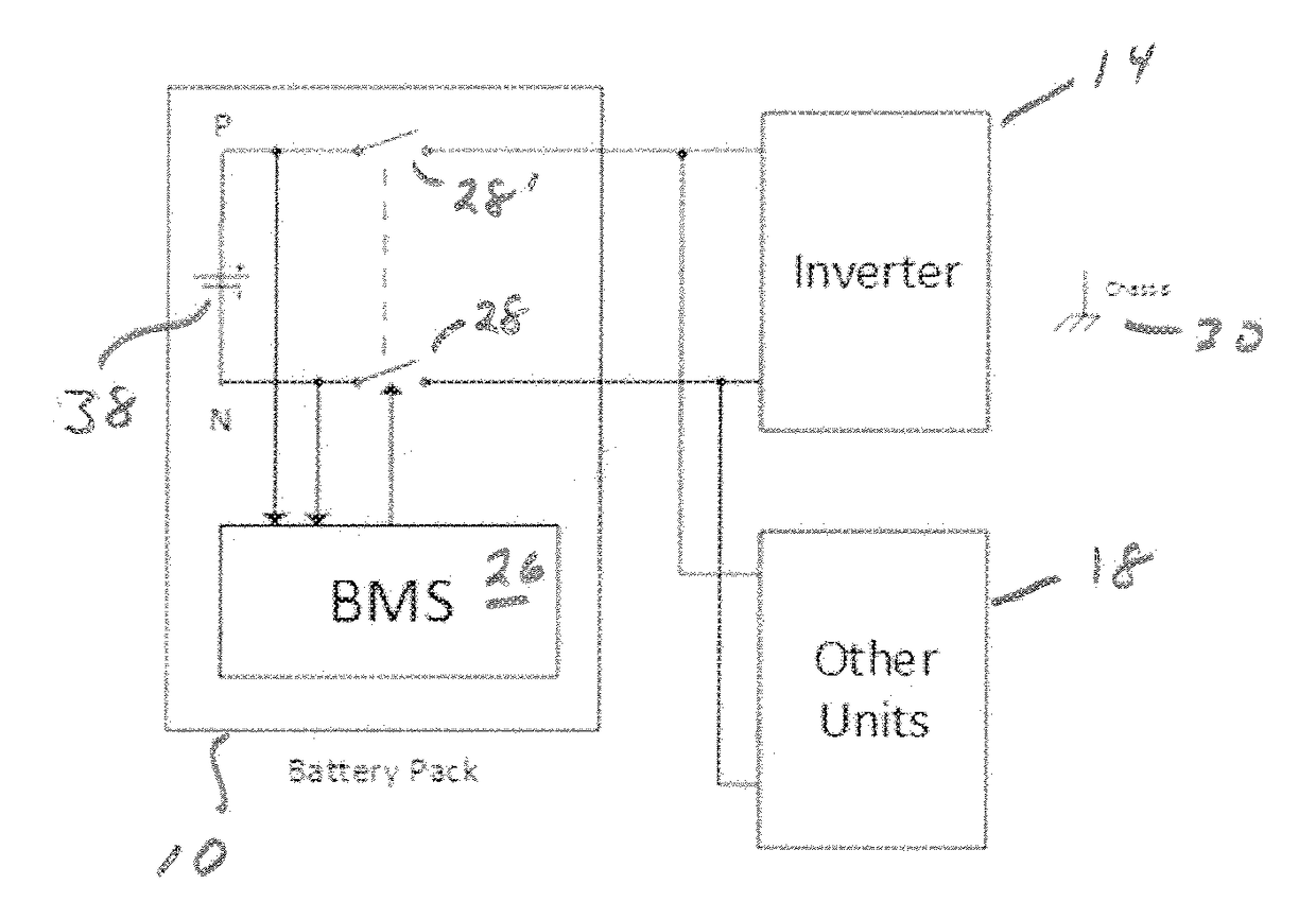
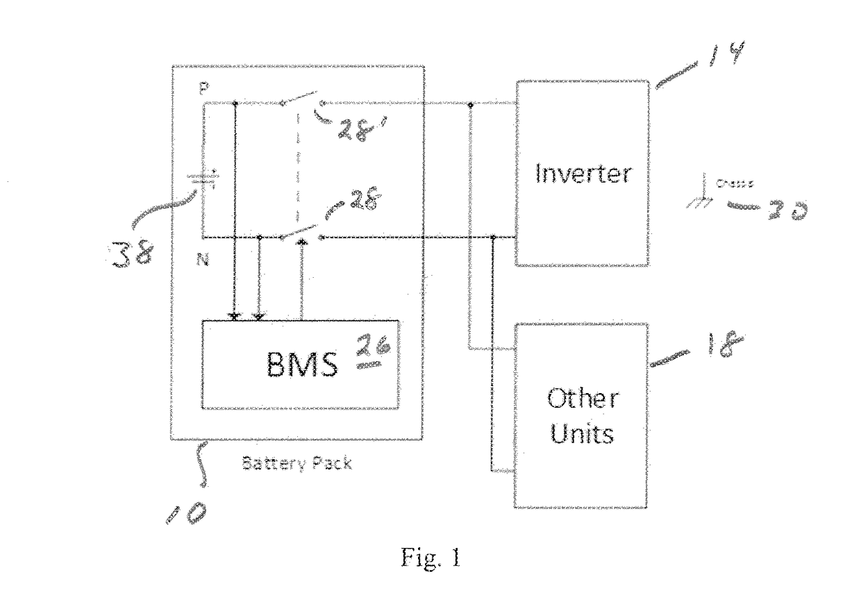
[0021]Referring to FIG. 1, an embodiment of a vehicle electrical system is depicted with a battery pack 10 connected to an inverter 14 and other electrical components 18 that draw current from the battery pack 10. The battery pack 10 includes a battery 38, a battery management system 26 that monitors the battery voltage, and a pair of relays 28, 28′ c...


PUM


Abstract

A method for measuring the isolation resistance between a chassis and a battery terminal in an electric vehicle. The method can include measuring an open voltage (VP(open)) of the positive terminal; measuring an open voltage (VN(open)) of the negative terminal; measuring a voltage (VN(S1 closed)) between the negative terminal and the chassis with switch S1 closed; measuring a voltage (VP(S1 closed)) between the positive terminal and the chassis with switch S1 closed; calculating the ratio (VP(open)/VN(closed)) of the voltages VP(open) and VN(closed); calculating the open ratio of the open voltages (VP(open)/VN(open)); calculating the difference between the ratio (VP(S1 closed)/VN(S1 closed)) and the open ratio (VP(open)/VN(open)); and multiplying the value of the test resistor (R0) by the difference between the ratio (VP(S1 closed)/(VN(S1 closed)) and the open ratio (VP(S2 open)/VN(S1 open)) to obtain the isolation resistance.

Description

FIELD OF THE INVENTION[0001]The invention relates generally to the electrical isolation of the chassis in electric vehicles and more specifically the measurement of such isolation.BACKGROUND OF THE INVENTION[0002]Electrically motorized vehicles such as electric vehicles (EV), hybrid electric vehicles (HEV), and fuel cell electric vehicles (FCEV) typically use high voltages (400-700 V) in the drive system to be able to provide high power to the drive motors. The distribution system for this high voltage is electrically isolated by insulation on the electric wires from the vehicle chassis. The isolation is designed to prevent an electrical shock hazard but can fail over time or due to a crash, which creates a potential electrocution hazard.[0003]Society of Automotive Engineers standard SAE J1766 proposes a method to measure the insulation resistance in such a vehicle in order to monitor the health of the insulation system to insure the vehicle is safe to operate. In the SAEJ1766 test ...

Claims


Application Information

Patent Timeline
Patent Type & Authority Applications(United States)
IPC IPC(8): G01R31/00G01R31/12
CPCG01R31/12G01R31/006G01R27/16G01R27/025G01R31/007G01R31/14
Inventor SCHULZ, STEVEN E.
Owner FARADAY&FUTURE INC
Why Eureka
Try Eureka