Computer Numerical Control Servo Drive System

a servo drive and computer numerical control technology, applied in computer control, program control, instruments, etc., can solve the problems of human errors and inability to effectively reduce equipment costs, and achieve the effect of enhancing power utilization efficiency and reducing equipment costs

Inactive Publication Date: 2017-06-22
CHEN FENG TIEN
View PDF9 Cites 0 Cited by
  • Summary
  • Abstract
  • Description
  • Claims
  • Application Information

AI Technical Summary

Benefits of technology

[0006]An objective of the present invention is to provide a computer numerical control (CNC) servo drive system utilizing a co-connection circuit for a driver to simultaneously drive multiple servo motors, thereby enhancing power utilization efficiency and reducing equipment cost.

Problems solved by technology

In case of mass production, not only may human errors arise from the necessity of inputting control commands to each control box 92, but the equipment cost is unable to be effectively lowered since the control box 91 can just control the single one piece of machining equipment.

Method used


Image

  • Computer Numerical Control Servo Drive System
  • Computer Numerical Control Servo Drive System
  • Computer Numerical Control Servo Drive System

Examples


Embodiment Construction

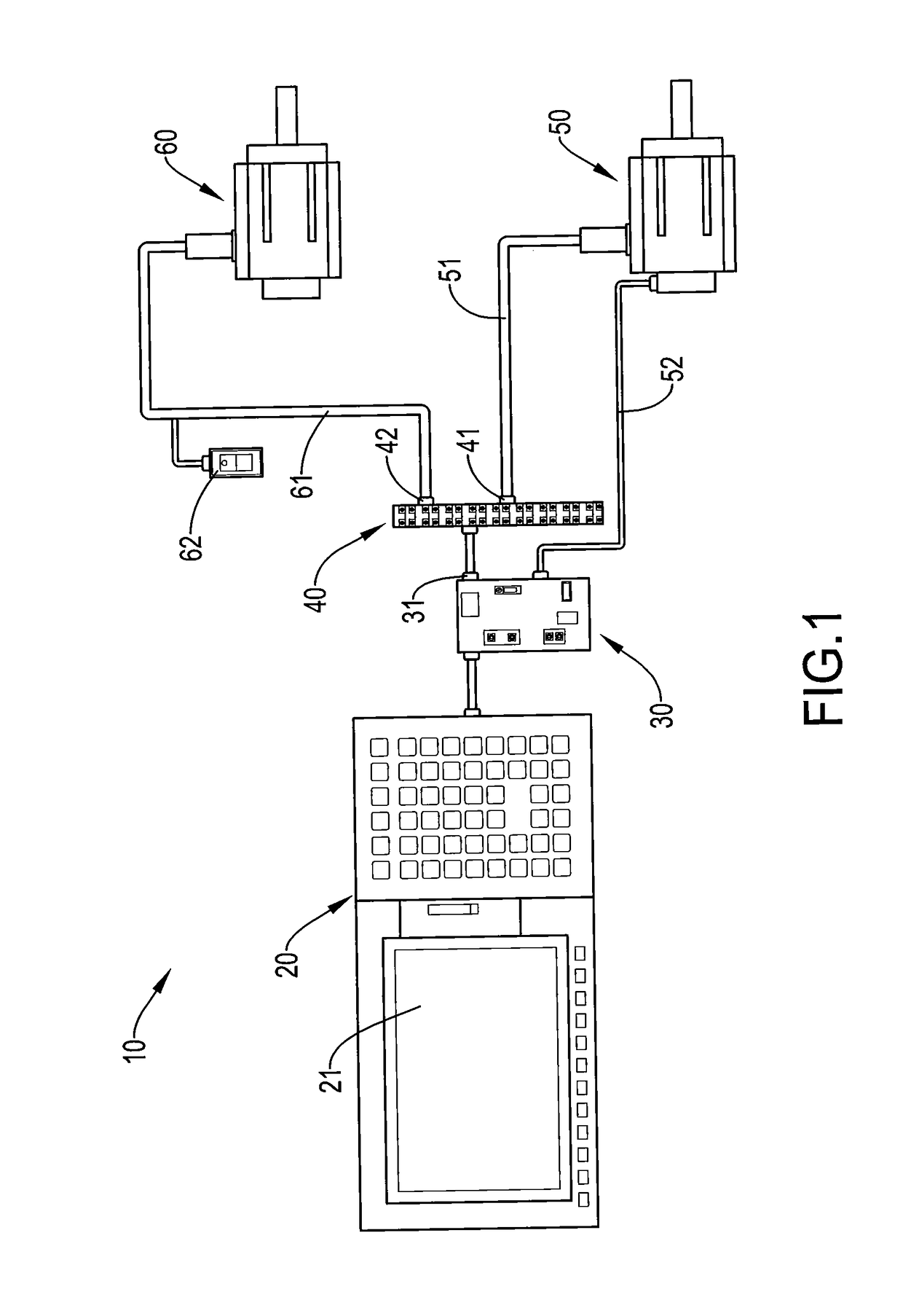
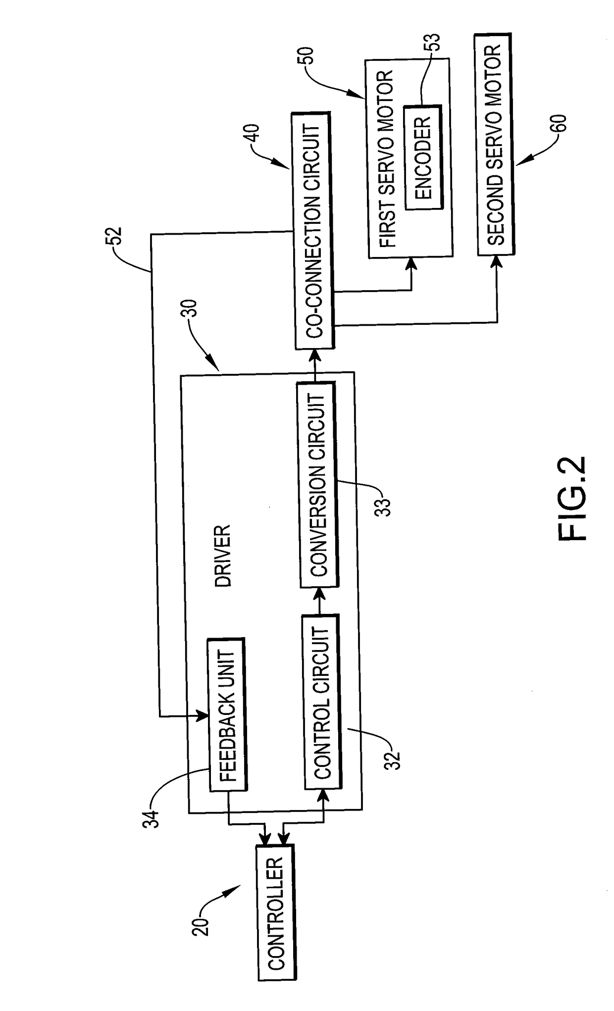
[0021]With reference to FIG. 1, a computer numerical control (CNC) servo drive system 10 in accordance with the present invention includes a controller 20, a driver 30, a co-connection circuit 40, a first servo motor 50 and a second servo motor 60. The controller 20 receives a user-inputted control command, converts the control command into a control signal, and outputs the control signal. The driver 30 is connected to the controller 20 and has an output terminal 31. After the driver 30 receives and converts the control signal, the output terminal 31 outputs a drive signal and an operating power. The co-connection circuit 40 transmits the drive signal and the operating power and has a first output terminal 41 and a second output terminal 42. The first output terminal 41 and the second output terminal 42 output the drive signal and allocate the operating power.

[0022]The first servo motor 50 is connected to the first output terminal 41 through a first power line 51, receives the opera...


PUM


Abstract

A computer numerical control (CNC) servo drive system includes a controller, a driver, a co-connection circuit, a first servo motor and a second servo motor. Users input a control command through the controller. The driver is connected to the controller, converts the control command into a drive signal, and outputs the drive signal. The co-connection circuit is connected to the driver and transmits the drive signal. A sum of maximum current values of the first servo motor and the second servo motor is not greater than a maximum current value of the driver, such that the driver can simultaneously drive the first servo motor and the second servo motor for operation.

Description

BACKGROUND OF THE INVENTION[0001]1. Field of the Invention[0002]The present invention relates to a computer numerical control (CNC) servo drive system and, more particularly, to a system capable of simultaneously driving multiple servo motors through a controller and a driver.[0003]2. Description of the Related Art[0004]Servo motors of CNC servo drive systems can perform accurate control over location and motion thereof, such as rotation speed, fast switch of forward and reverse rotation, accurate positioning and the like, and are oftentimes applied to automation of numerically controlled processes in car industry or for metal working machines. The working concepts of the CNC servo drive system reside in that users input a command to a controller, and after compilation of the command, control information is transmitted to a driver for the driver to drive a servo motor to perform motion, such as moving a tool, cutting or milling a workpiece with a tool, and the like, according to the...

Claims


Application Information

Patent Timeline
Patent Type & Authority Applications(United States)
IPC IPC(8): G05B19/404
CPCG05B2219/34429G05B19/404G05B19/4142
Inventor CHEN, FENG-TIEN
Owner CHEN FENG TIEN
Why Eureka
Try Eureka