
Lane Detection System And Method

a detection system and lane technology, applied in the field oflane detection system and method, can solve the problems of complex hardware implementation, computational complexity, and noise sensitivity

Active Publication Date: 2017-06-22
OMNIVISION TECH INC
View PDF3 Cites 38 Cited by
  • Summary
  • Abstract
  • Description
  • Claims
  • Application Information

AI Technical Summary

Benefits of technology

The patent is about a system that can detect lanes on a road image based on a lane marker. The system uses a non-volatile memory and an image processor to process the road image and identify a lane candidate. The system checks if the lane candidate is a true lane by measuring the distance between a near subregion and a predetermined reference point. The system then extends the true lane candidate into a far subregion to create a detected lane marker that demarcates the lane. The technical effect of this system is to enable the detection of lanes on road images, which can help in various applications such as autonomous driving.

Problems solved by technology

Conventional lane-detection algorithms rely on feature detection schemes that include at least one of the following drawbacks: noise sensitivity, computational complexity, and complex hardware implementation.

Method used


Image

  • Lane Detection System And Method
  • Lane Detection System And Method
  • Lane Detection System And Method

Examples


Embodiment Construction

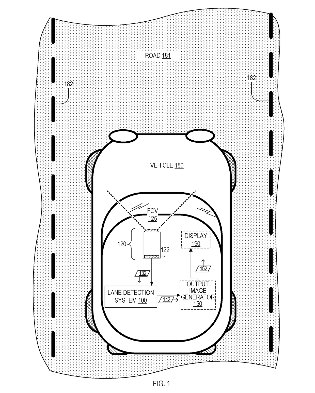
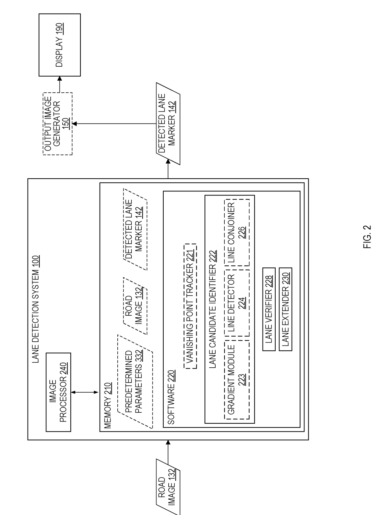
[0016]FIG. 1 is a plan view showing one exemplary lane detection system 100 used within a vehicle 180. Vehicle 180 is on a road 181 that has lane markers 182. Lane detection system 100 includes an image processor 240. Vehicle 180 includes a camera 120 and optionally a display 190 communicatively coupled to lane detection system 100. Camera 120 includes an image sensor having a pixel array 122. In an embodiment, lane detection system 100 includes at least one of camera 120 and display 190.

[0017]Lane detection system 100 receives a road image 132 of a portion of road 181 within a field of view 125 of camera 120. Lane detection system 100 processes at least part of road image 132 to detect one or more lane markers 182 and generate a corresponding one or more detected lane markers 142. Detected lane markers 142 are for example one or more of an image demarcating lane markers 182 and an equation (or data set of coordinates) representable as a line or curve superimposable on road image 13...


PUM


Abstract

A lane detection system includes a non-volatile memory storing machine-readable instructions and an image processor capable of receiving a road image. The image processor, when executing the machine-readable instructions, is capable of: (i) processing the road image to identify a lane candidate within a lane-existing region of the road image, the lane-existing region having (a) a near subregion including an imaged road region nearer to the vehicle and (b) a far subregion including an imaged road region farther from the vehicle, (ii) verifying the lane candidate as a true lane candidate when a minimum distance between (a) a line fit to a portion of the lane candidate in the near subregion and (b) a predetermined reference point in the road image is less than a neighborhood distance; and (iii) extending the true lane candidate into the far subregion to form a detected lane marker demarcating the lane marker.

Description

BACKGROUND[0001]An increasing number of new road vehicles are equipped with a lane departure warning system designed to monitor the position of the vehicle with respect to a lane boundary on a road. Central to a lane departure warning system is a robust lane marker detection algorithm module to provide meaningful and consistent lane information for driving safety and navigation purposes. Conventional lane-detection algorithms rely on feature detection schemes that include at least one of the following drawbacks: noise sensitivity, computational complexity, and complex hardware implementation.SUMMARY OF THE INVENTION[0002]The disclosed lane detection system and method overcomes problems of conventional lane-detection schemes. In an embodiment, a method detects a lane within a road image captured from the front of a vehicle traveling along a road having a lane marker. The method includes processing the road image to identify a lane candidate within a lane-existing region of the road i...

Claims


Application Information

Patent Timeline
IPC IPC(8): G06K9/00G06T7/00
CPCG06K9/00798G06T7/0081G06T2207/30256G06T2207/20036G06T7/0091G06V20/588G06T7/12G06T7/155G06T7/11
Inventor YANG, LEIWU, DONGHUI
Owner OMNIVISION TECH INC
Learn More