Hollow cathode ion source

a technology of hollow cathode and ion source, which is applied in the direction of basic electric elements, electric discharge tubes, electrical apparatus, etc., can solve the problems of adding additional components to problems with vacuum hardware or processes, and the use of neutralizers, etc., to achieve the effect of improving the overall ion source and reducing the cost of production

Active Publication Date: 2017-06-22
ASAHI GLASS CO LTD +2
View PDF4 Cites 12 Cited by
  • Summary
  • Abstract
  • Description
  • Claims
  • Application Information

AI Technical Summary

Benefits of technology

[0009]Embodiments of the present invention comprise hollow-cathode-based ion sources of surprising simplicity. Embodiments of the present invention can create an energetic ion beam without requiring any additional electr

Problems solved by technology

The additional components also add complexity to the overall ion source.
This electrical imbalance can create problems with vacuum hardware or processes.
As with the other additional components, the use of a neutralizer adds complexity to the overall ion source.
These components often add significant degrees of mechanical and process complexity to an ion source.
Further, when using a hollow cathode as the plasma-forming component, known ion sources rely on a dedicated anode structure or separate anodic orifice,

Method used


Image

  • Hollow cathode ion source
  • Hollow cathode ion source
  • Hollow cathode ion source

Examples


Embodiment Construction

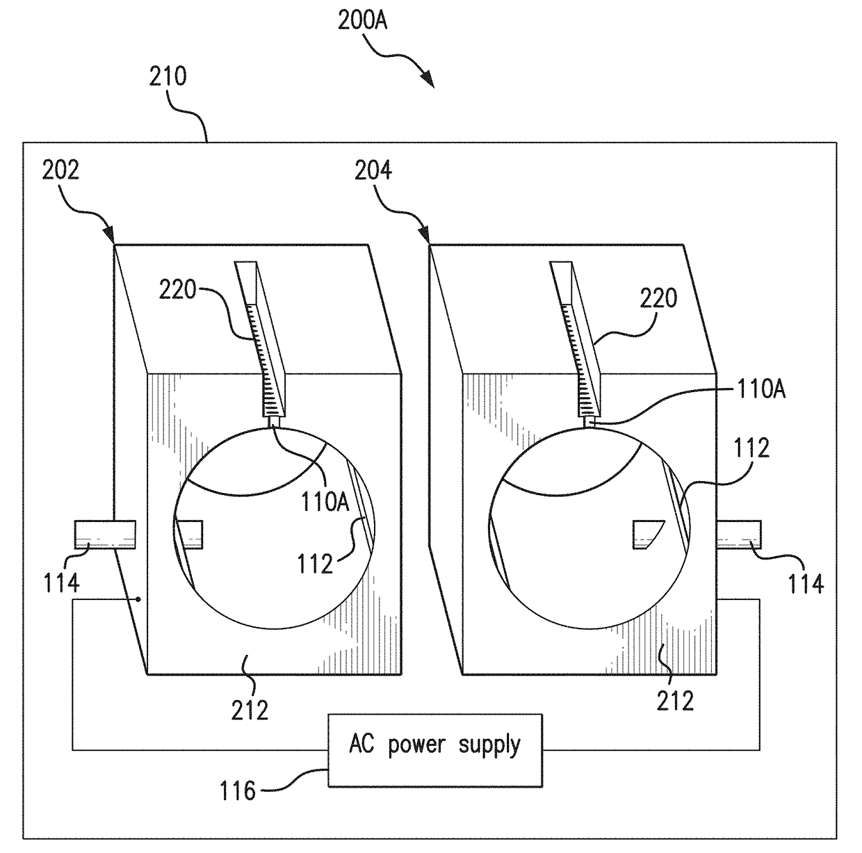
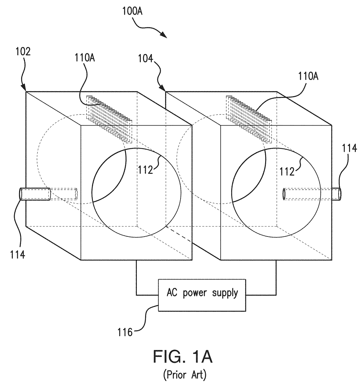
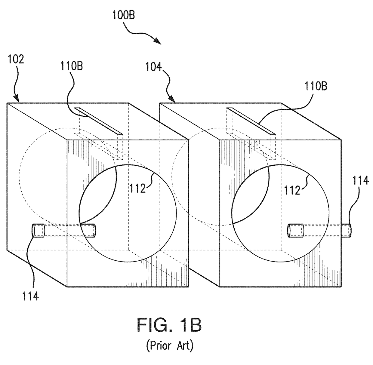
[0043]FIGS. 1A, 1B, and IC, illustrate known hollow cathode plasma sources 100A, 100B, 100C. As shown in FIG. 1A, hollow cathode plasma source 100A includes a first linear hollow cathode 102 and a second linear hollow cathode 104, each connected to power source 116. Each linear hollow cathode 102, 104 includes an interior hollow cathode cavity 112 and a gas inlet 114 to allow plasma-forming gasses to enter into the hollow cathode cavity 112. Additionally, the hollow cathodes 102, 104 include a plasma exit region. As shown in FIG. 1A, the plasma exit region consists of an array of holes or nozzles 110A leading from the hollow cathode cavity 112 to the process chamber that houses the hollow cathodes. As shown in FIG. 1B, the plasma exit region consists of a single slot 110B in the hollow cathode body. FIG. 1C shows a tubular or cylindrical point hollow cathode plasma source, including tubular hollow cathodes 102C, 104C each having a hollow cathode cavity 112C and a gas inlet 114C, ana...


PUM


Abstract

An ion source includes a chamber. The ion source further includes a first hollow cathode having a first hollow cathode cavity and a first plasma exit orifice and a second hollow cathode having a second hollow cathode cavity and a second plasma exit orifice. The first and second hollow cathodes are disposed adjacently in the chamber. The ion source further includes a first ion accelerator between and in communication with the first plasma exit orifice and the chamber. The first ion accelerator forms a first ion acceleration cavity. The ion source further includes a second ion accelerator between and in communication with the second plasma orifice and the chamber. The second ion accelerator forms a second ion acceleration cavity. The first hollow cathode and the second hollow cathode are configured to alternatively function as electrode and counter-electrode to generate a plasma. Each of the first ion acceleration cavity and the second ion acceleration cavity are sufficient to enable the extraction and acceleration of ions.

Description

BACKGROUND OF THE INVENTION[0001]Ion sources are commonly used for a variety of applications, including substrate treatment in the form of heating, cleaning, surface etching, and chemically modifying a surface. Ion sources can be used for depositing oxides, diamond-like carbon, and other useful coatings. Ion sources can be used to support vacuum deposition processes and to modify thin film growth. For example, ion sources can be used to densify, crystalize, or chemically react with depositing atoms. Virtually all ion sources are designed to operate in the reduced pressure of a vacuum chamber. Some ion sources can be used as low-thrust, long-running engines for spacecraft acceleration.[0002]In their most basic form, ion sources typically consist of a plasma-forming component with additional components to extract and accelerate ions from that plasma. These additional components typically create electric or magnetic fields within the plasma gas other than fields created by the plasma-f...

Claims


Application Information

Patent Timeline
IPC IPC(8): H01J37/32
CPCH01J37/32596H01J37/3244H01J37/32458H01J37/08H01J2237/0041H01J2237/061H01J2237/31
Inventor CHAMBERS, JOHNMASCHWITZ, PETER
Owner ASAHI GLASS CO LTD
Why Eureka
Try Eureka