
High-voltage intelligent switch alternating current capacitor

a high-voltage, intelligent switch technology, applied in the direction of fixed capacitor details, temperature compensation, ac network circuit arrangements, etc., can solve the problems of high cost, high power consumption of capacitor fling-cut switching, and complex reactive power compensation equipment, so as to achieve greatly lower cost and increase the reliability of the switch

Active Publication Date: 2017-06-22
GYRK INT TECH
View PDF2 Cites 3 Cited by
  • Summary
  • Abstract
  • Description
  • Claims
  • Application Information

AI Technical Summary

Benefits of technology

The present patent provides a high-voltage AC capacitor with a built-in intelligent switch for fling-cut switching the capacitor without causing sparking or arcing, which improves safety and reliability. The design allows for the integration of the switch and capacitor, reducing volume and cost, and multiple low-voltage intelligent switches in series solves the problem of air contact switches cannot be connected in series to form a high-voltage switch. The intelligent switch control module provides many kinds of protection measures for the capacitor to ensure timely protection when the capacitor is over heated, over current, or over voltage. The high-voltage intelligent switch has a built-in discharge unit, which produces almost no power consumption during operating of the capacitor. The present patent also provides an intelligent switch AC capacitor with extra high-voltage and ultra high-voltage for compensation of extra high-voltage or ultra high-voltage.

Problems solved by technology

Low power factors lead to serious line loss.
Because it is easier to switch a reactor in a manner of fling-cut switching rather than to switch a capacitor, a capacitor is generally adopted to generate a static negative reactive power so as to adjust change of reactive power using a method of switching a reactor in a manner of fling-cut switching or adjusting a saturated electronic controller, which apparently causes complexity of a reactive power compensation equipment.
Using a thyristor as a fling-cut switch can solve a fling-cut switching problem of a capacitor (a SVC technology); and although thyristor fling-cut switching can avoid an inrush current during capacitor fling-cut switching, the capacitor fling-cut switching has a defect of high power consumption and high cost.
At present, in an occasion that a frequency of the capacitor fling-cut switching is not high, a commonly adopted manner is to adopt vacuum circuit breaker for fling-cut switching; however, the vacuum circuit breaker cannot avoid an inrush current during fling-cut switching.
To solve such a problem, series reactors are generally adopted to suppress surge voltage and surge current, which will increase cost of a compensation device.
A Chinese patent application No. 201110034379.4 has disclosed a high-voltage electronic arc extinguishing switch, which is formed of a plurality of switch contacts in series; however, this application requires that a withstand voltage between each relay contact and control coils should be over a controlled total voltage, which places great demands on insulation between contacts of a relay and coils.
For security reasons regarding a high-voltage AC capacitor, many detection and protection devices for capacitor are generally installed in a compensation equipment; however, these detection and protection devices are external and are unable to detect operating situations inside the capacitor, thus so-called protection is lagging and inaccurate.
Although there is a low cost due to use of discharging resistor, a great power consumption would occur.
Therefore, a discharging coil with high cost is generally connected to both ends of an AC capacitor in parallel; however, the discharging coil would also produce certain power consumption during operation of a compensation capacitor.
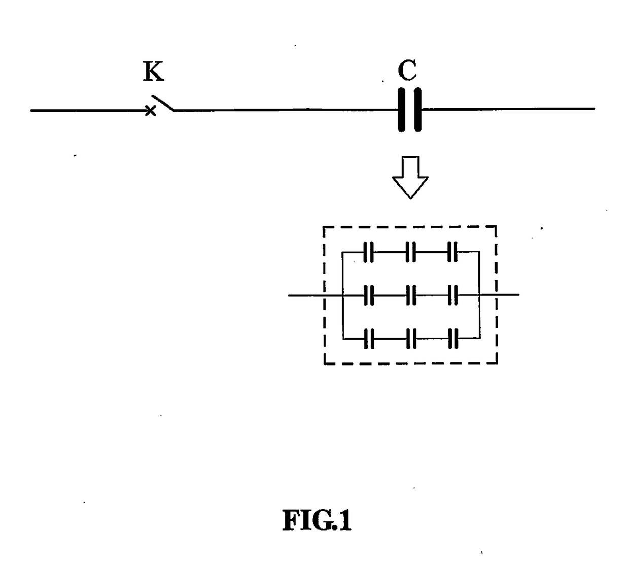
Even though a capacitor for reactive power compensation on a power grid, and a fling-cut switch are always used together, but they always appear as two components, which increases not only hidden danger due to poor connection between the two components, but also cost of the two components.
In addition, it is not easy for actual designers and users of a reactive power compensation capacitor to select a proper fling-cut switch, since different capacitors in use need to be coordinated with different fling-cut switches.
Capacitor core packages produced by a thin film metalizing process are widely used in a low-voltage field due to advantages of cost and environmental protection; however, capacitor core packages produced by the thin film metalizing process cannot be used in a field of high-voltage capacitors since a thin film metalized capacitor in use continually decays in capacity, and a capacitor core package decayed in capacity would further accelerate decay in capacity due to increasing of a partial pressure if thin film metalized capacitors are connected in series, so that lives of thin film metalized capacitor core packages connected in series in a high-voltage capacitor are short.
Consumption of the switch is much lower than that of a thyristor fling-cut switch or a vacuum circuit breaker switch, and fling-cut speed of the switch is equivalent to that of a thyristor fling-cut switch; however, reliability of the switch is greatly higher than that of a thyristor switch, and cost of the switch is greatly lower than that of a thyristor switch.

Method used


Image

  • High-voltage intelligent switch alternating current capacitor
  • High-voltage intelligent switch alternating current capacitor
  • High-voltage intelligent switch alternating current capacitor

Examples


Embodiment Construction

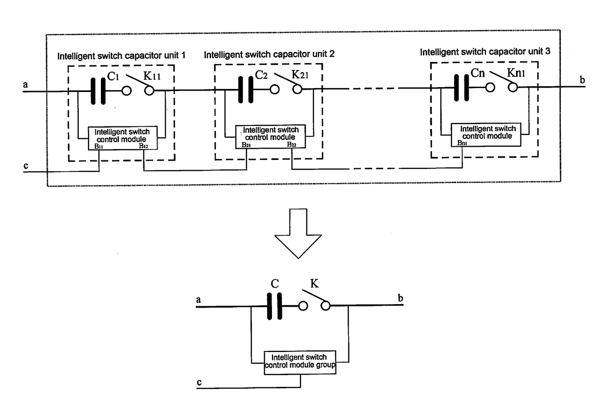
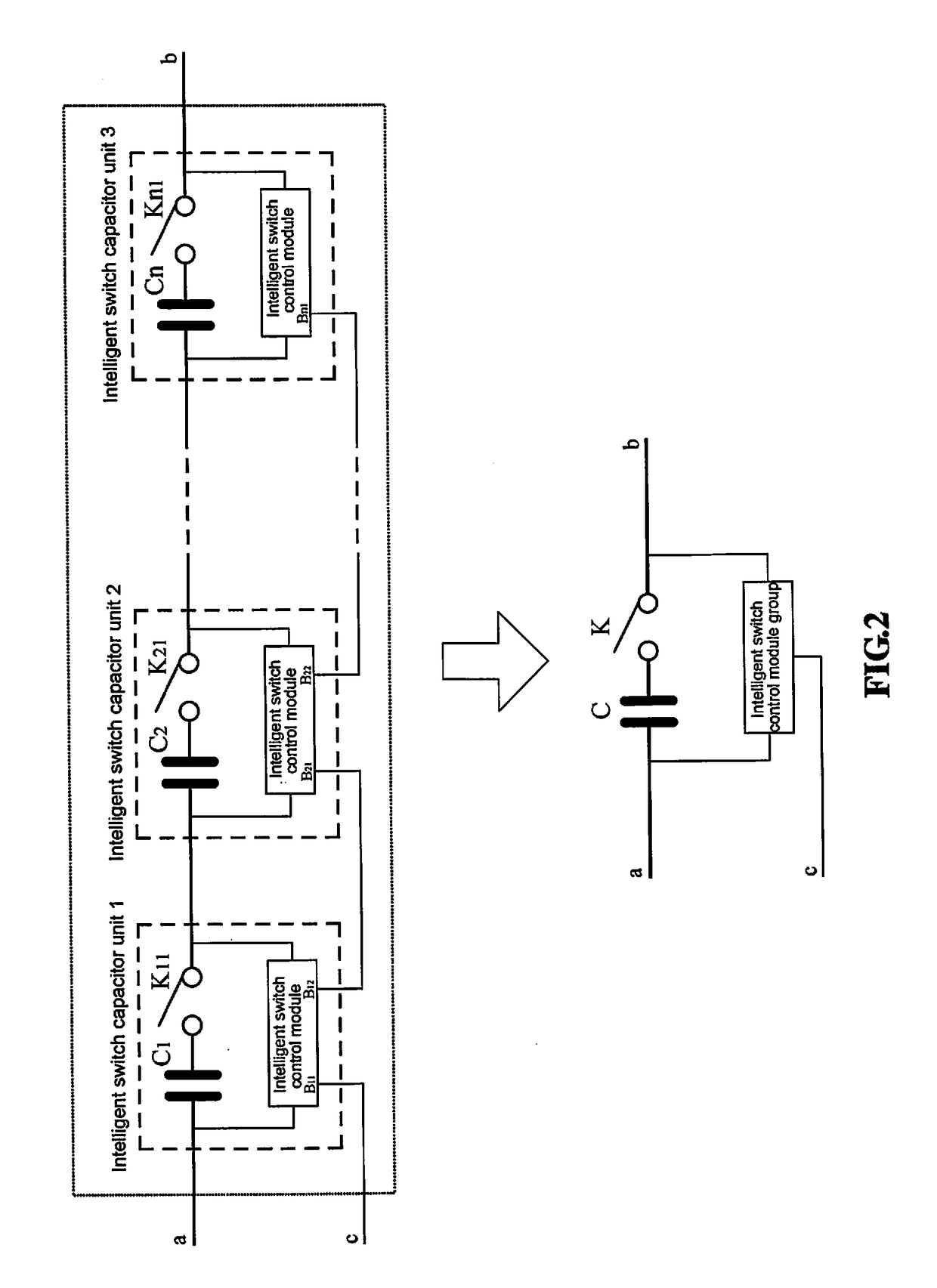
[0033]A high-voltage intelligent switch AC capacitor of the present disclosure is a new type of circuit element that contains a high-voltage intelligent switch and a high-voltage AC capacitor, and has a control end c capable of controlling operations of a high-voltage switch K, as shown in FIG. 2. A intelligent switch capacitor unit is composed of an intelligent switch control module, a relay switch and an AC capacitor, where a contact of the relay switch is connected with the capacitor in series, and the intelligent switch control module is connected to both ends of the series circuit including the contact of the relay switch and the capacitor, and the intelligent switch control module has a high-voltage end communication interface and a low-voltage end communication interface. A specific series mode of intelligent switch capacitor units is shown in FIG. 2, usually a capacitor end of a high-voltage intelligent switch capacitor is connected to a low-voltage end of a power grid, and ...


PUM


Abstract

Disclosed is a high-voltage AC capacitor for reactive power compensation of 10 kV-35 kV power grid, and in particular to a high-voltage AC capacitor with a high-voltage switching switch provided therein, as well as a structure for prolonging the service life of a thin film metalized high-voltage capacitor and a control method for prolonging the service life of the thin film metalized high-voltage capacitor. The AC capacitor is formed by multiple intelligent switch capacitor units connected in series, and each capacitor unit is formed by a switch contact (K11-Kn1) and a capacitor (C1-Cn) connected in series. If there are N capacitor units, when each switch contact is disconnected, the endurable voltage of each switch contact, the endurable voltage between the switch contact and a coil and the voltage each capacitor withstands are 1 / Nth of the total voltage; when the switch operates, all the contacts operate at the same instant, the switch contacts are prevented from striking sparks or discharging arcs under the protection of the contact protection circuits, and the high-voltage switch is realized through multiple air contact switches connected in series.

Description

TECHNICAL FIELD[0001]The present disclosure relates to a high-voltage capacitor for reactive power compensation of 10 kV-35 kV power grid, in particular to a combination of a high-voltage fling-cut switch and a high-voltage alternating current (AC) capacitor.TECHNICAL BACKGROUND[0002]Power equipments in a power system mainly are inductive equipments. Low power factors lead to serious line loss. In order to ensure an economic operation of a power grid, there is a parallel capacitor compensation device equipped to a main load side (10 kV or 35 kV) of each transformer substation of respective voltage grade. Positive reactive power produced by a perceptual device in the power grid constantly changes, so that negative reactive power produced by a corresponding compensation capacitor would also change correspondingly. Because it is easier to switch a reactor in a manner of fling-cut switching rather than to switch a capacitor, a capacitor is generally adopted to generate a static negative...

Claims


Application Information

Patent Timeline
IPC IPC(8): H02J3/18H01G4/258H01G4/255
CPCH02J3/1807H01G4/258H01G4/255Y02E40/30
Inventor WANG, HAI
Owner GYRK INT TECH
Learn More