
Transmitter

Active Publication Date: 2017-06-22
SK HYNIX INC
View PDF5 Cites 0 Cited by
  • Summary
  • Abstract
  • Description
  • Claims
  • Application Information

AI Technical Summary

Benefits of technology

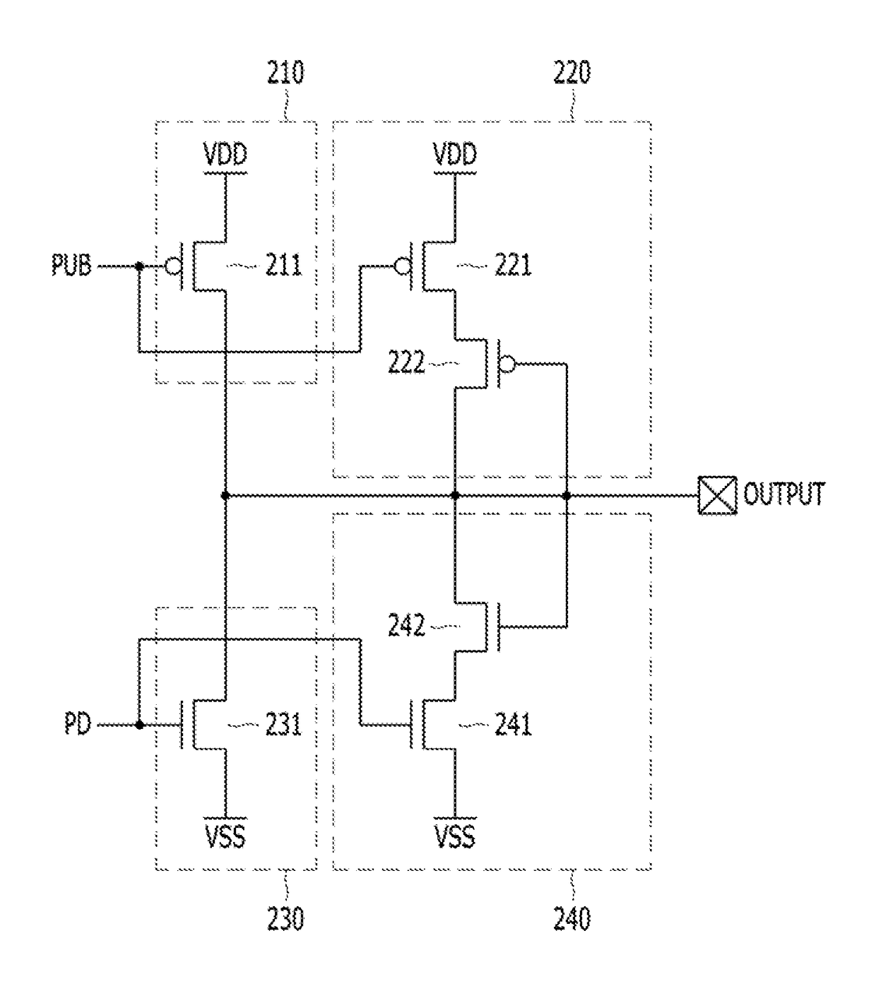
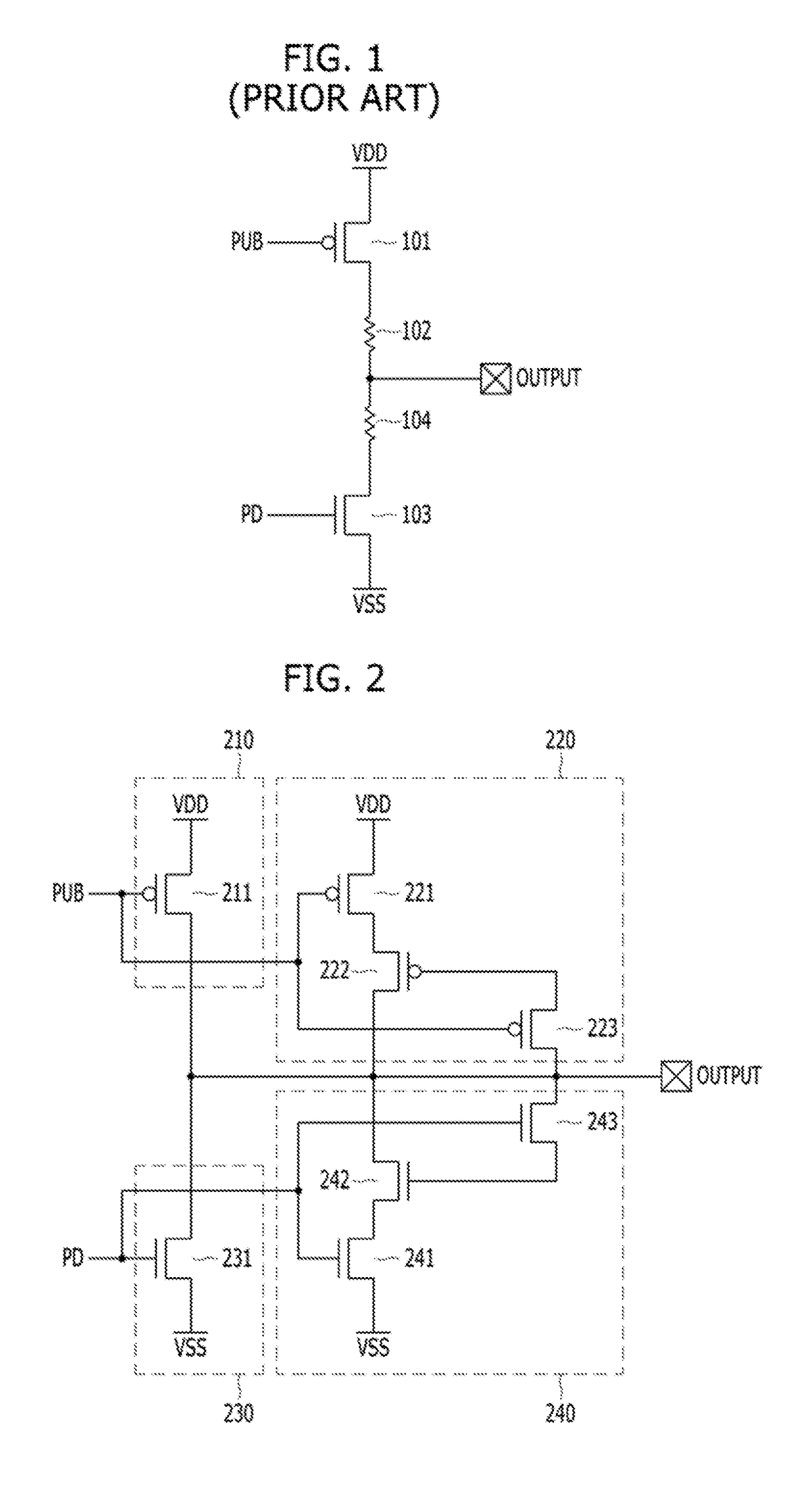
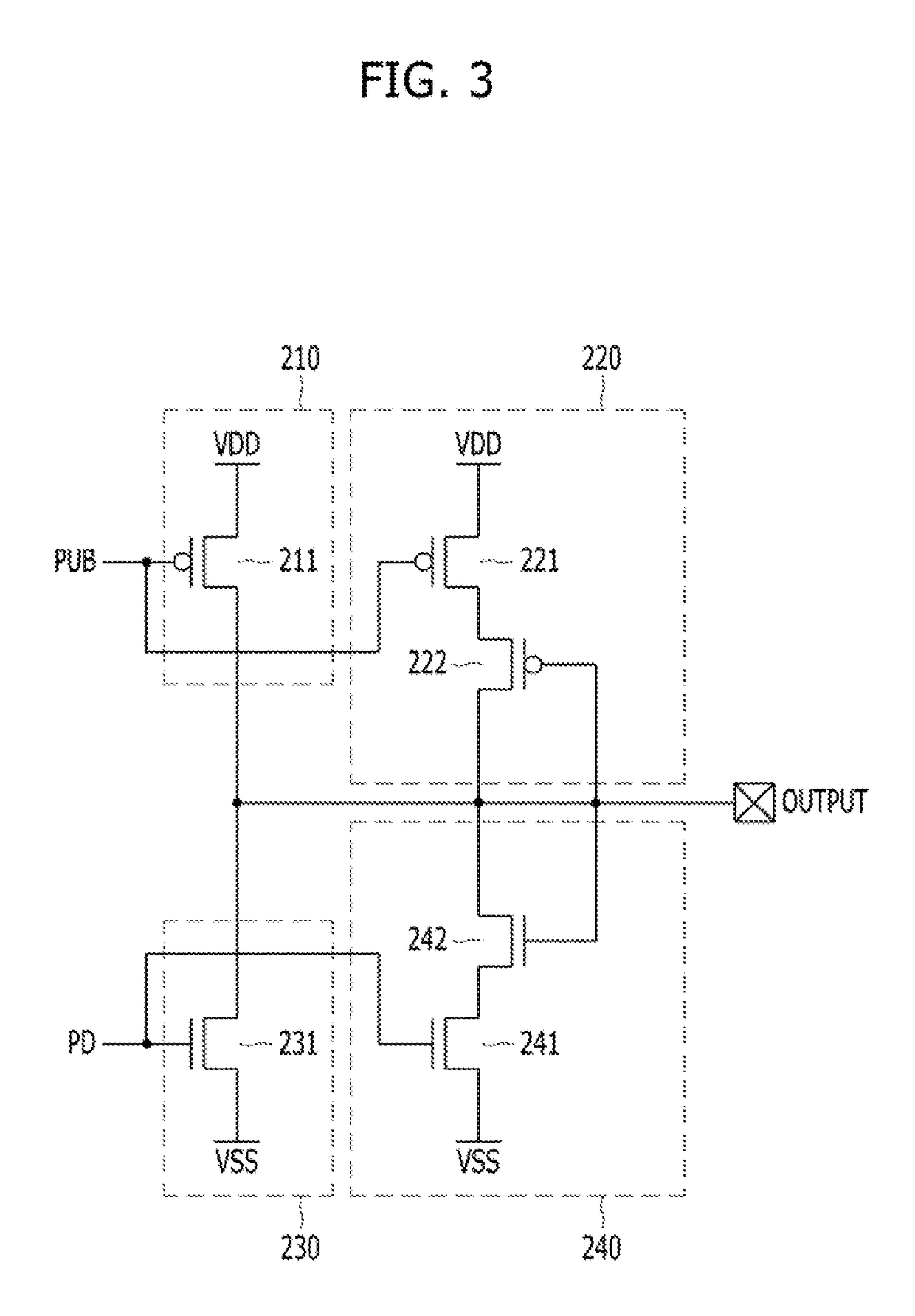
The invention is about a transmitter that can secure the linearity of its driving current without using passive resistors. It includes a main pull-up driver and an auxiliary pull-up driver for pull-up driving the output node. The main pull-down driver and an auxiliary pull-down driver are also included for pull-down driving. The main pull-up driver includes a first PMOS transistor for pull-up driving the output node, a second PMOS transistor for applying a pull-up voltage, a third PMOS transistor for transmitting the voltage of the output node, and a fourth PMOS transistor for pull-down driving the output node. The auxiliary pull-down driver includes a second NMOS transistor for applying a pull-down voltage, a third NMOS transistor for transmitting the voltage of the output node, and a fourth NMOS transistor for pull-down driving the output node using the pull-down voltage. The transmitter can compensate for non-linear driving current characteristics of its drivers and can be used in various applications.

Problems solved by technology

As a result, it may be difficult for the transmitter to operate at a high speed.

Method used


Image

  • Transmitter
  • Transmitter
  • Transmitter

Examples


Embodiment Construction

[0031]Various embodiments will be described below in more detail with reference to the accompanying drawings. The present invention may, however, be embodied in different forms and should not be construed as limited to the embodiments set forth herein. Rather, these embodiments are provided so that this disclosure will be thorough and complete, and will fully convey the scope of the present invention to those skilled in the art. Throughout the disclosure, like reference numerals refer to like parts throughout the various figures and embodiments of the present invention.

[0032]The drawings are not necessarily to scale and, in some instances, proportions may have been exaggerated to clearly illustrate features of the embodiments. It is also noted that in this specification, “connected / coupled” refers to one component not only directly coupling another component, but also indirectly coupling another component through an intermediate component. In addition, a singular form may include a ...


PUM


Abstract

A transmitter includes: a main pull-up driver suitable for pull-up driving an output node; and an auxiliary pull-up driver suitable for pull-up driving the output node based on a voltage of the output node, wherein the auxiliary pull-up driver compensates for non-linear driving current characteristics of the main pull-up driver.

Description

TECHNICAL FIELD[0001]Various embodiments of the present invention relate to a transmitter for transmitting signals to and from an integrated circuitBACKGROUND[0002]Integrated circuits may operate by exchanging signals with peripheral devices. For example, memory devices, such as DRAMs and flash memory devices may exchange signals with a memory controller. Also, central processing units (CPUs) may exchange data with a variety of semiconductor memory devices on a mother board. Furthermore signal transmission may be performed between integrated circuits of different devices as well as between integrated circuits included inside the same semiconductor device. A circuit for transmitting signals is typically referred to as a transmitter or an output driver.DISCUSSION OF THE RELATED ART[0003]FIG. 1 is a diagram illustrating a conventional transmitter.[0004]Referring to FIG. 1, a conventional transmitter includes a P-type metal-oxide-semiconductor (PMOS) transistor 101 a resistor 102, an N-...

Claims


Application Information

Patent Timeline
IPC IPC(8): H03K17/693G05F3/16
CPCG05F3/16H03K17/693
Inventor KIM, JAE-HEON
Owner SK HYNIX INC
Learn More