Zinc oxide resistor and its manufacturing method

Inactive Publication Date: 2006-07-27
NAT INST FOR MATERIALS SCI
View PDF4 Cites 0 Cited by
  • Summary
  • Abstract
  • Description
  • Claims
  • Application Information

AI Technical Summary

Benefits of technology

[0020] It is an another object of the present invention to provide a zinc oxide resistor structure capable of achieving an α-value, or a performance index of a zinc oxide varistor, of about 20 or more, which is equivalent to that of a conventional typical polycrystalline varistor device, and joining zinc-oxide single crystals with a high junction strength in an obtained artificial grain boundary, so as to eliminate the risk of peeling of the zinc-oxide single crystals during use.
[0023] The present invention provides a structure and production method for achieving zinc oxide varistor characteristics conventionally achieved in a zinc oxide sintered body, by a multilayer comprising a pair of opposed single crystals and a glass layer forming an oxide grain boundary layer. Thus, differently from a conventional varistor consisting of polycrystalline body, the technique of joining the opposed single crystals makes it possible to provide enhanced controllability of a resistor so as to obtain a varistor having an intended function.
[0028] Instead of simply joining the zinc-oxide single crystals, an intervening layer containing bismuth oxide is formed in the junction interface between the zinc-oxide single crystals to enhance the nonlinear current-voltage characteristic of the zinc oxide varistor.
[0030] If the bismuth oxide layer intervening between the grain boundaries in the joined unit of the zinc-oxide single crystals is crystallized, the mechanical strength of the joined unit is likely to be spoiled, as described above. Thus, the grain boundary layer of the joined unit is formed of a bismuth-and-boron-containing oxide glass phase. In a process of forming this glass phase, the boron oxide added to the bismuth-containing layer residing in the junction interface can accelerate vitrification of the grain boundary layer by taking advantage of its feature of a low melting point.

Problems solved by technology

This causes difficulties in setting the number of grains or each size of grains in a ceramics at a predetermined value.
While this technique can achieve a current-voltage characteristic with high nonlinearity, it still involves a problem about strength of a junction between the opposed zinc-oxide single crystals.
While a certain level of mechanical strength is achieved in the varistor device disclosed in the Non-Patent Publication 4, the varistor device without any intervening grain-boundary layer has a poor performance, wherein an α-value as a performance index of varistor characteristics is less than 10.
Similarly, adequate varistor characteristics are not achieved in the varistor device disclosed in the Non-Patent Publication 5, due to no intervening grain-boundary layer.

Method used


Image

  • Zinc oxide resistor and its manufacturing method
  • Zinc oxide resistor and its manufacturing method
  • Zinc oxide resistor and its manufacturing method

Examples


example

Inventive Example 1

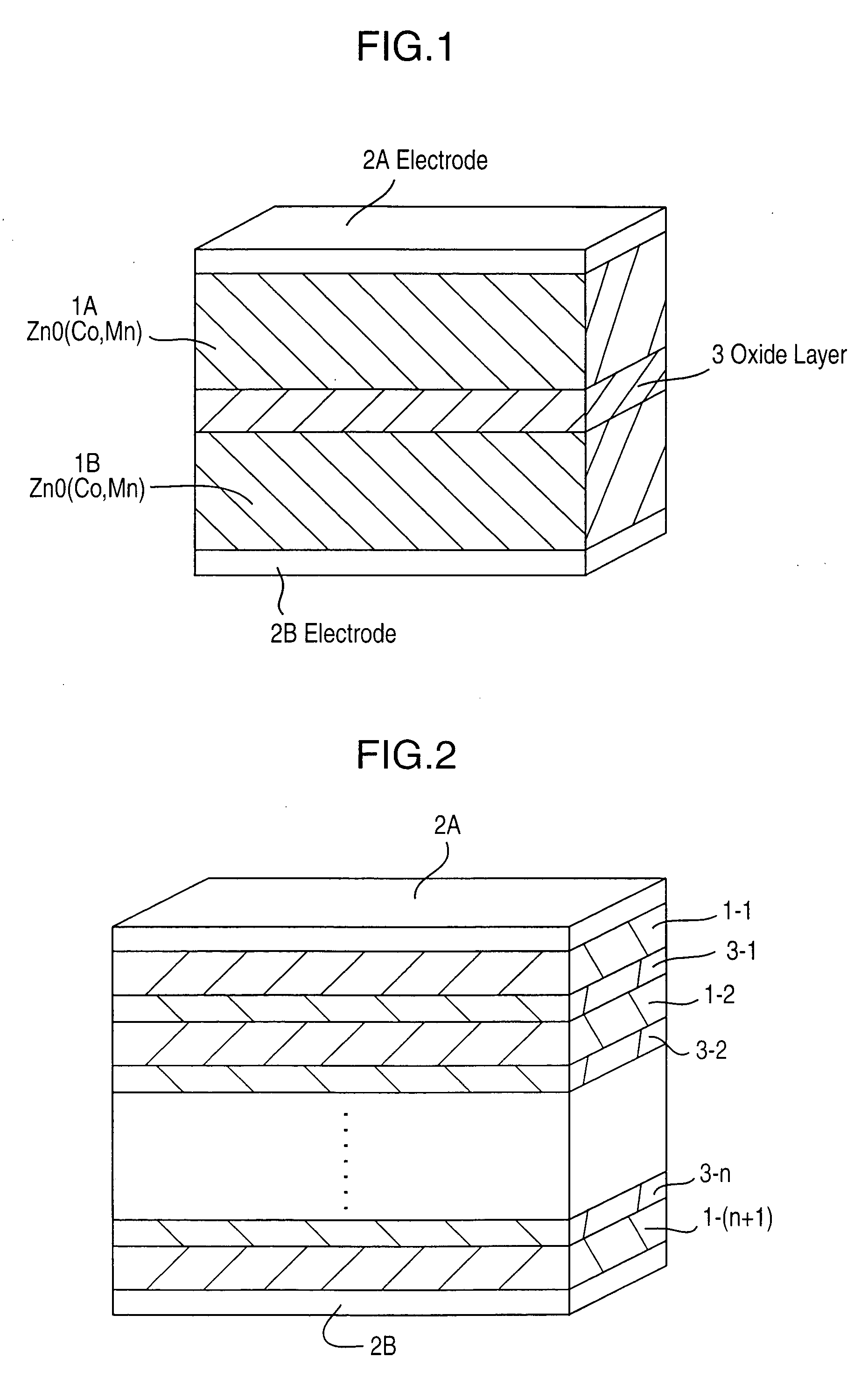
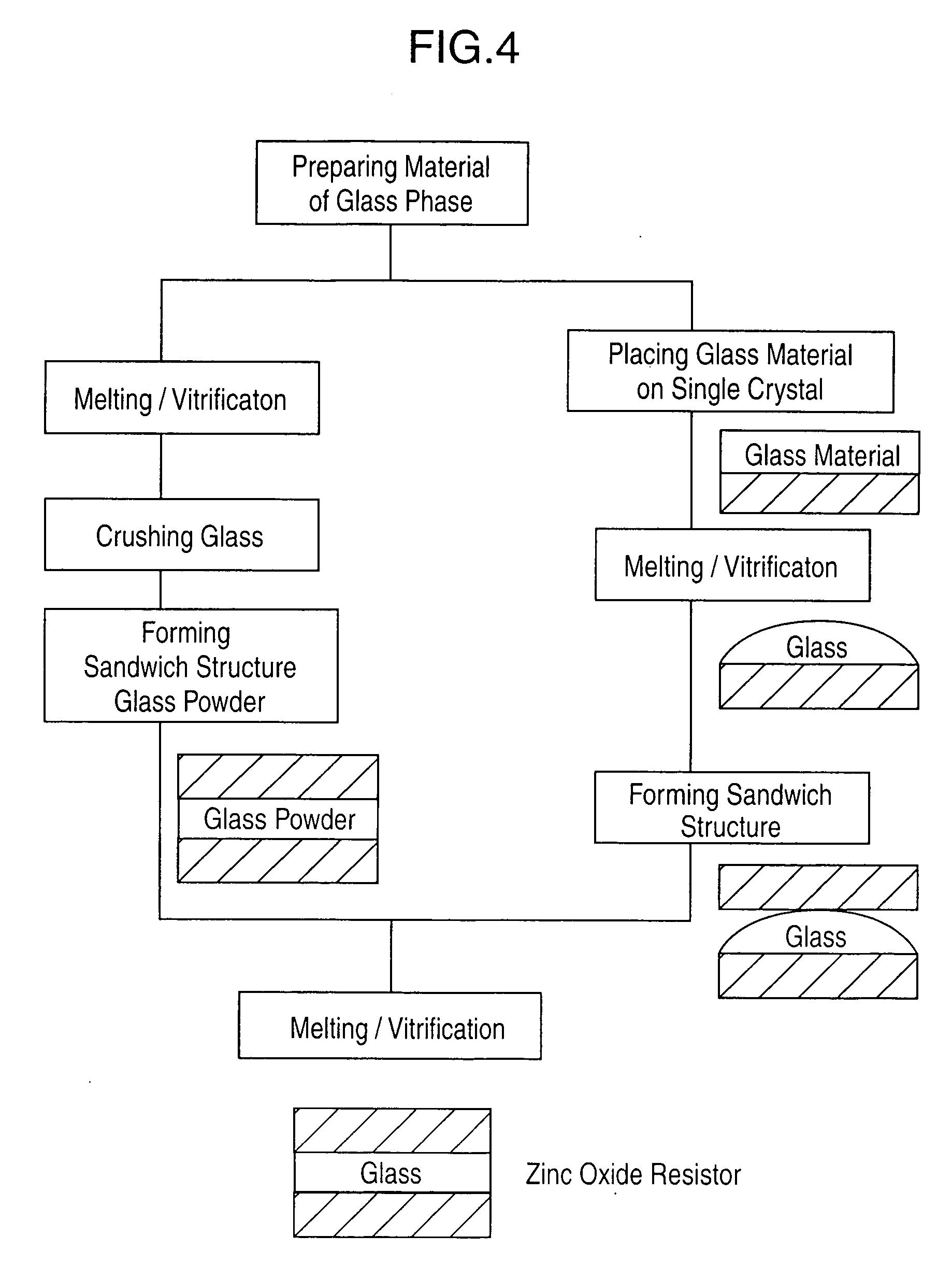
[0072] Each of two zinc-oxide single crystals was in contact with a cobalt-oxide sintered body, in an oxygen flow at 1200° C. for 3 hours to diffuse cobalt into each zinc-oxide single crystal so as to prepare two cobalt-doped zinc-oxide single crystals. A quantity of the resulting solid solution of cobalt was calculated as about 1 at % based on optical spectrum. Then, 0.8772 g of boron oxide, 8.8068 g of bismuth oxide, 0.1517 g of cobalt oxide and 0.16431 g of manganese oxide were measured and mixed together. The obtained mixture was put in a platinum crucible, and molten at 900° C. in an oxygen flow. Then, the molten mixture was flowed out of the crucible, and solidified to obtain a bismuth-and-boron-containing oxide glass. After crushing the glass, the obtained glass powder was dredged on one of the prepared cobalt-doped zinc-oxide single crystals (5×5×0.5 mm), and another zinc-oxide single crystal was superimposed on the single crystal with the glass powder to...

##ventive example 2

Inventive Example 2

[0074] Each of two zinc-oxide single crystals was in contact with a cobalt-oxide sintered body, in an oxygen flow at 1200° C. for 12 hours to diffuse cobalt into each zinc-oxide single crystal so as to prepare two cobalt-doped zinc-oxide single crystals. Then, 0.8772 g of boron oxide, 8.8068 g of bismuth oxide, 0.1517 g of cobalt oxide and 0.16431 g of manganese oxide were measured and mixed together. The obtained mixture was put in a platinum crucible, and molten at 900° C. in an oxygen flow. Then, the molten mixture was flowed out of the crucible, and solidified to obtain a bismuth-and-boron-containing oxide glass. After crushing the glass, the obtained glass powder was dredged on one of the prepared cobalt-doped zinc-oxide single crystals (5×5×0.5 mm), and another zinc-oxide single crystal was superimposed on the single crystal with the glass powder to form a sandwich structure.

[0075] Without particular pressing, the sandwich structure was heated at 1000° C. i...


PUM


Abstract

Disclosed are a zinc oxide resistor structure, and methods of forming a glass layer and a resistor, which are required for producing the resistor structure. The zinc oxide resistor comprises zinc oxide grains and an oxide glass layer which contains bismuth and boron and intervenes between the zinc oxide grains. The oxide glass layer residing between the zinc oxide grains changes the electric properties between the grains to achieve a higher resistance and a non-ohmic characteristic of a voltage-dependent resistance value in the resistor. This non-ohmic characteristic can be applied, particularly, to a non-ohmic device to be compatible with a low-voltage operation. Differently from conventional resistors, the oxide glass layer intervening between the zinc oxide grains can achieve an enhanced mechanical strength of a junction in the device.

Description

TECHNICAL FIELD [0001] The present invention relates to a zinc oxide resistor, and more particularly a varistor device structure for protecting an electric / electronic circuit from surge voltages, and a production method thereof. BACKGROUND ART [0002] 1. Typical Zinc Oxide Varistor [0003] Generally, a zinc oxide varistor is provided as a polycrystalline zinc-oxide ceramics. Specifically, the zinc oxide varistor has been produced by mixing zinc oxide powder, transition metal oxide powder and bismuth oxide powder, and burning the mixture at a high temperature, to form a polycrystalline body with a structure in which a bismuth oxide or the like is segregated in the boundaries between zinc oxide grains each containing a transition metal oxide dissolved therein in the form of a solid solution (see, for example, the following Non-Patent Publication 1). [0004] An appropriate additive makes it possible for the zinc oxide ceramics to exhibit a nonlinear current-voltage characteristic in which...

Claims


Application Information

Patent Timeline
IPC IPC(8): H01C7/10H01C7/112
CPCH01C7/112H01C7/10
Inventor OHASHI, NAOKIHANEDA, HAJIMESAKAGUCHI, ISAOOHGAKI, TAKESHIKATAOKA, KEN
Owner NAT INST FOR MATERIALS SCI
Why Eureka
Try Eureka