
Varistor and method for manufacturing varistor

a manufacturing method and varistor technology, applied in the direction of resistor details, resistors adapted for applying terminals, positive temperature coefficient thermistors, etc., can solve problems such as degrading electrical characteristics, and achieve the effects of reducing varistor capacitance, increasing resistance of the entire surface, and adjusting the electric resistance of the high-resistance region

Active Publication Date: 2013-01-24
TDK CORPARATION
View PDF5 Cites 0 Cited by
  • Summary
  • Abstract
  • Description
  • Claims
  • Application Information

AI Technical Summary

Benefits of technology

The present invention provides a method for manufacturing a varistor that can reduce capacitance while maintaining good nonlinear current-voltage characteristics. The method involves diffusing alkali metal from the surface of the varistor element body into the interior of the varistor element body prior to the external electrode forming step. This process forms a high-resistance region in a region exposed from the external electrodes in the surface of the varistor element body, which securely achieves an increase in resistance of the entire surface of the varistor element body.

Problems solved by technology

However, any one of them causes influence on electrical characteristics of the varistor (e.g., ESD tolerance and nonlinear current-voltage characteristic) and may degrade the electrical characteristics.

Method used


Image

  • Varistor and method for manufacturing varistor
  • Varistor and method for manufacturing varistor
  • Varistor and method for manufacturing varistor

Examples


Embodiment Construction

[0033]The preferred embodiments of the present invention will be described below in detail with reference to the accompanying drawings. In the description, the same elements or elements with the same functionality will be denoted by the same reference signs, without redundant description.

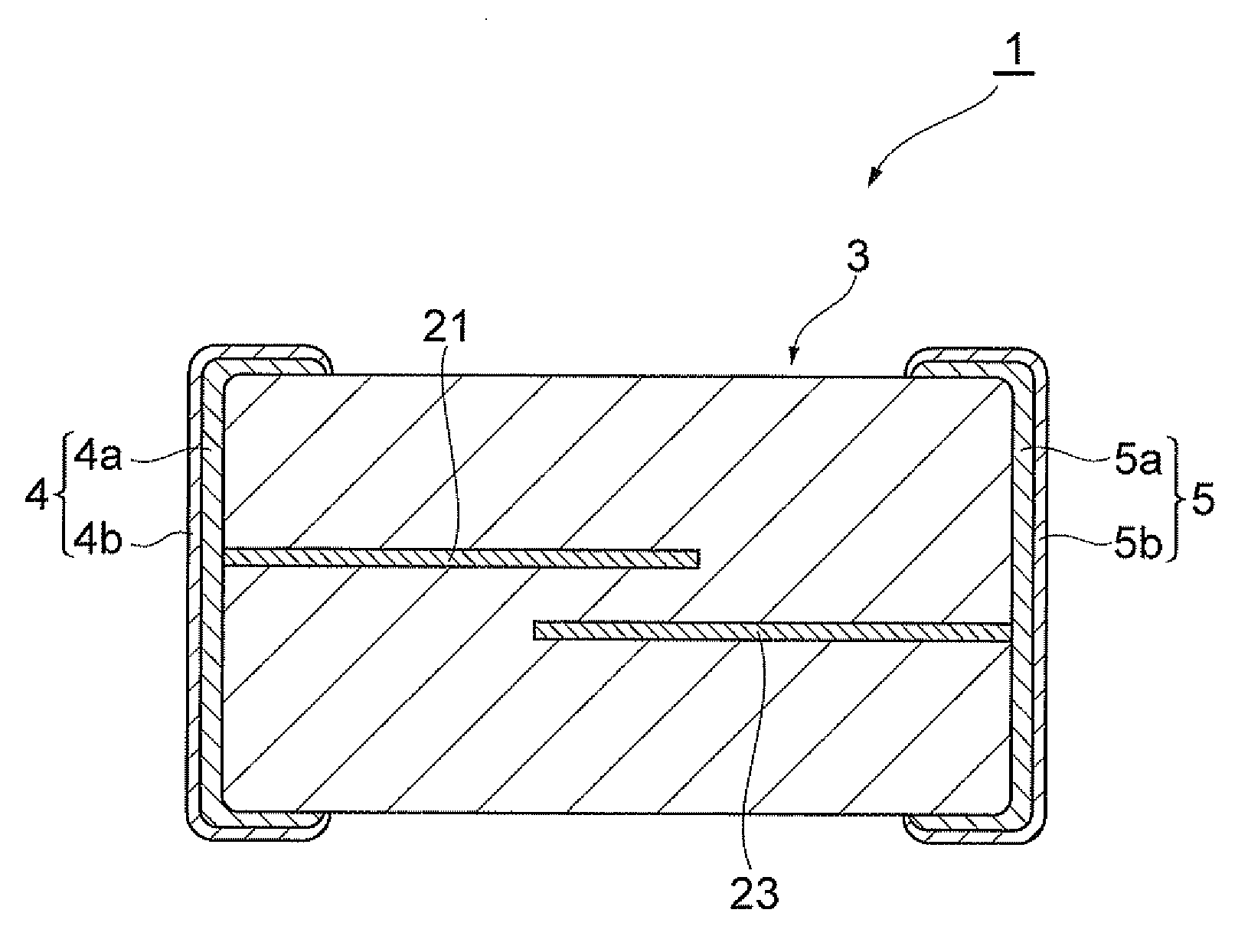
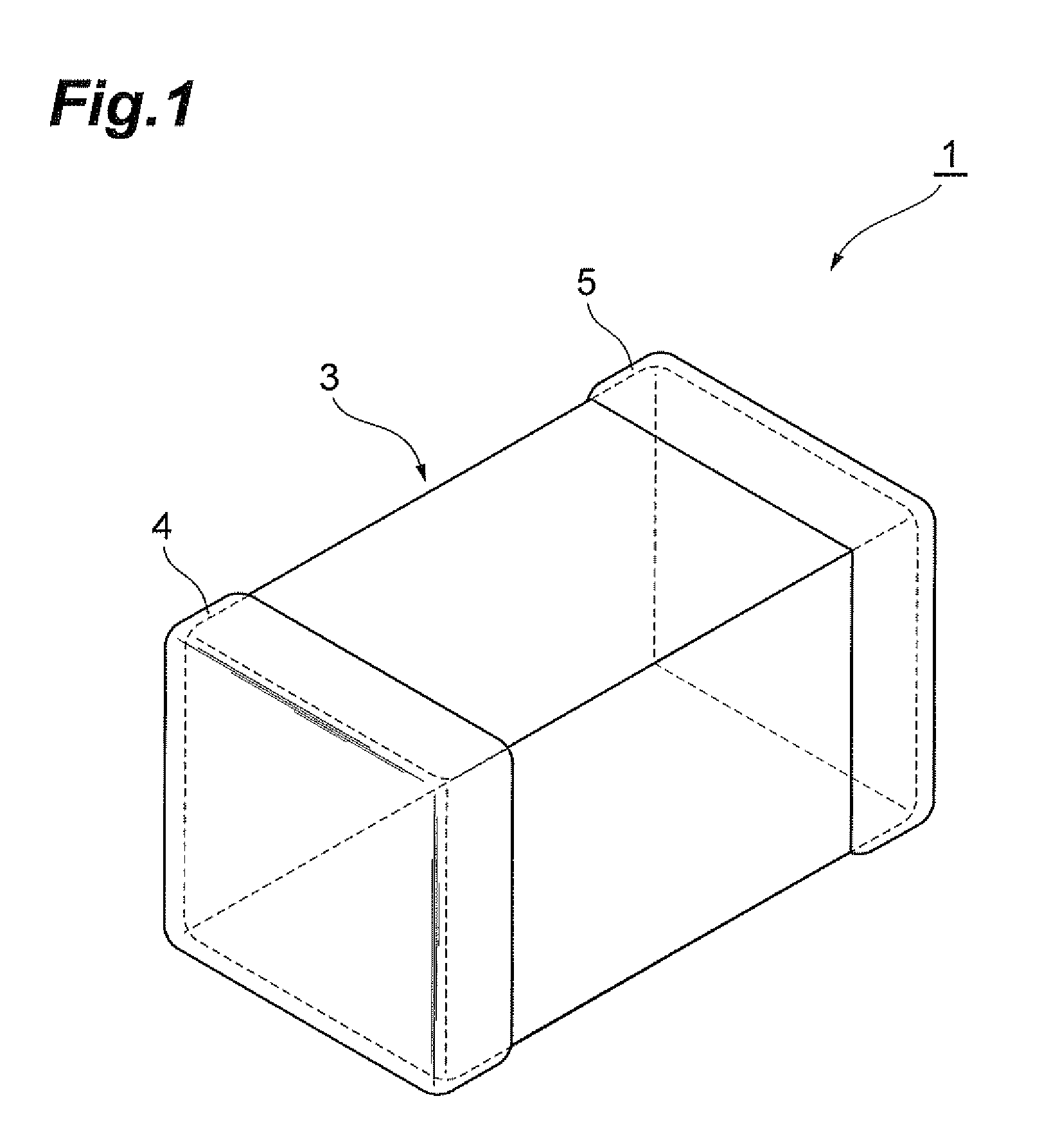
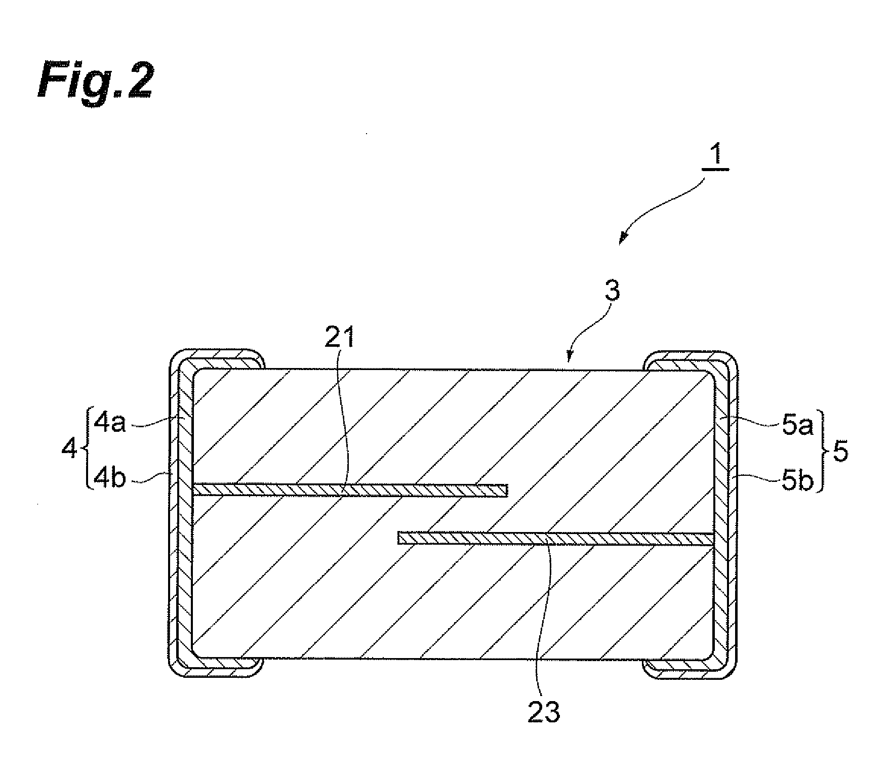
[0034]First, a configuration of multilayer chip varistor 1 according to an embodiment of the present invention will be described with reference to FIGS. 1 to 3. FIG. 1 is a perspective view showing the multilayer chip varistor according to the present embodiment. FIG. 2 is a drawing illustrating a cross-sectional configuration of the multilayer chip varistor according to the present embodiment. FIG. 3 is an exploded perspective view of a varistor element body in the multilayer chip varistor according to the present embodiment. The present embodiment will describe the multilayer chip varistor 1 as an example of varistor.

[0035]The multilayer chip varistor 1, as shown in FIGS. 1 and 2, has a varistor e...


PUM

PropertyMeasurementUnit
heightaaaaaaaaaa
widthaaaaaaaaaa
lengthaaaaaaaaaa

Abstract

A varistor is provided with a varistor element body, a plurality of internal electrodes arranged in the varistor element body so as to sandwich a partial region of the varistor element body between them, and a plurality of external electrodes arranged on the surface of the varistor element body and connected to the corresponding internal electrodes. The external electrode has a sintered electrode layer formed by attaching an electroconductive paste containing an alkali metal to the surface of the varistor element body and sintering it. The varistor element body has a high-resistance region formed by diffusing the alkali metal in the electroconductive paste into the varistor element body from an interface between the surface of the varistor element body and the sintered electrode layer.

Description

BACKGROUND OF THE INVENTION[0001]1. Field of the Invention[0002]The present invention relates to a varistor and a method for manufacturing the varistor.[0003]2. Related Background Art[0004]A known varistor is one having a varistor element body comprised of a semiconducting ceramic material to exhibit the nonlinear current-voltage characteristic, a plurality of internal electrodes arranged in the varistor element body so as to sandwich a partial region of the varistor element body between them, and a plurality of external electrodes arranged on the surface of the varistor element body and connected to the corresponding internal electrodes (e.g., cf Japanese Patent Application Laid-open No. H01-295403 (which will be referred to hereinafter as “Patent Literature 1”))SUMMARY OF THE INVENTION[0005]With recent increase in speed of digital signals and communication speed, there are demands for a low-capacitance varistor causing little influence on signals.[0006]It is an object of the prese...

Claims


Application Information

Patent Timeline
Patent Type & Authority Applications(United States)
IPC IPC(8): H01C7/10H01C17/00
CPCH01C1/14H01C7/00Y10T29/49085H01C17/28Y10T29/49082H01C7/10
Inventor TANAKA, HITOSHIMORIAI, KATSUNARIITAMI, TAKAHIRO
Owner TDK CORPARATION
Learn More