Methods and devices for optical signal encoding and decoding

Inactive Publication Date: 2017-06-29
KUANG CHI INTELLIGENT PHOTONIC TECH
View PDF8 Cites 8 Cited by
  • Summary
  • Abstract
  • Description
  • Claims
  • Application Information

AI Technical Summary

Benefits of technology

[0024]Beneficial effects of this application are as follows: According to the optical signal encoding and decoding methods and the device that are provided in this application, the following encoding steps are performed: converting to-be-sent data into corresponding N-ary data; reading N-ary data bit by bit, and encoding the data into electric signal units: encoding each different digit in the N-ary data into a different electric signal unit, where high level duration and low level duration in the electric signal unit are Ti1, Ti2, . . . , and Tij respectively, i, j, and N are natural numbers, and the different electric signal units are separated by delimiters; and combining the electric signal units corresponding to th

Problems solved by technology

However, when controlling on and off states of the LED flash, delay occurs randomly, and on and off duration of the LED flash cannot be controlled precisely.
Consequently, in an application of the mobile terminal such as a mobile phone, the LED flash works unstabitily when the LED flash is in a flashing state, which leads to

Method used


Image

  • Methods and devices for optical signal encoding and decoding
  • Methods and devices for optical signal encoding and decoding
  • Methods and devices for optical signal encoding and decoding

Examples


embodiment 1

[0037]Although control precision of an LED flash of a mobile terminal such as a mobile phone is not high, a control delay of the flash is basically within a range. In addition, the mobile terminal such as a mobile phone itself can roughly read on and off duration of the LED flash. According to this characteristic, this embodiment proposes new encoding and decoding methods. Specifically, from a perspective of an optical signal, presence of light and absence of light are used to represent information instead of using change of states between light and absence of light to represent information. From a perspective of an electric signal, a level continuation state is used to represent information instead of using a level transition to represent information.

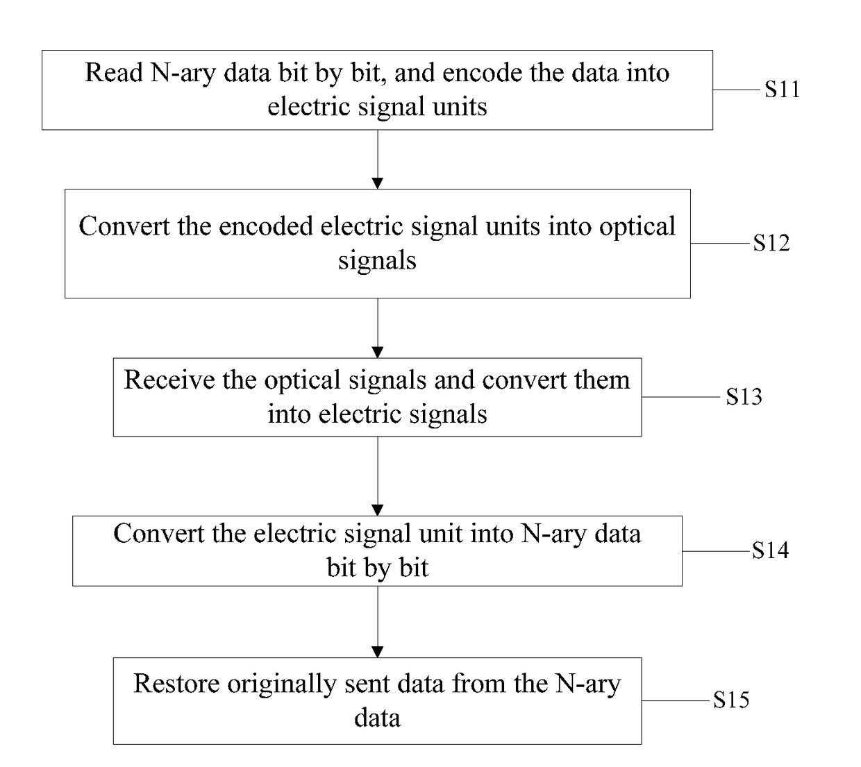
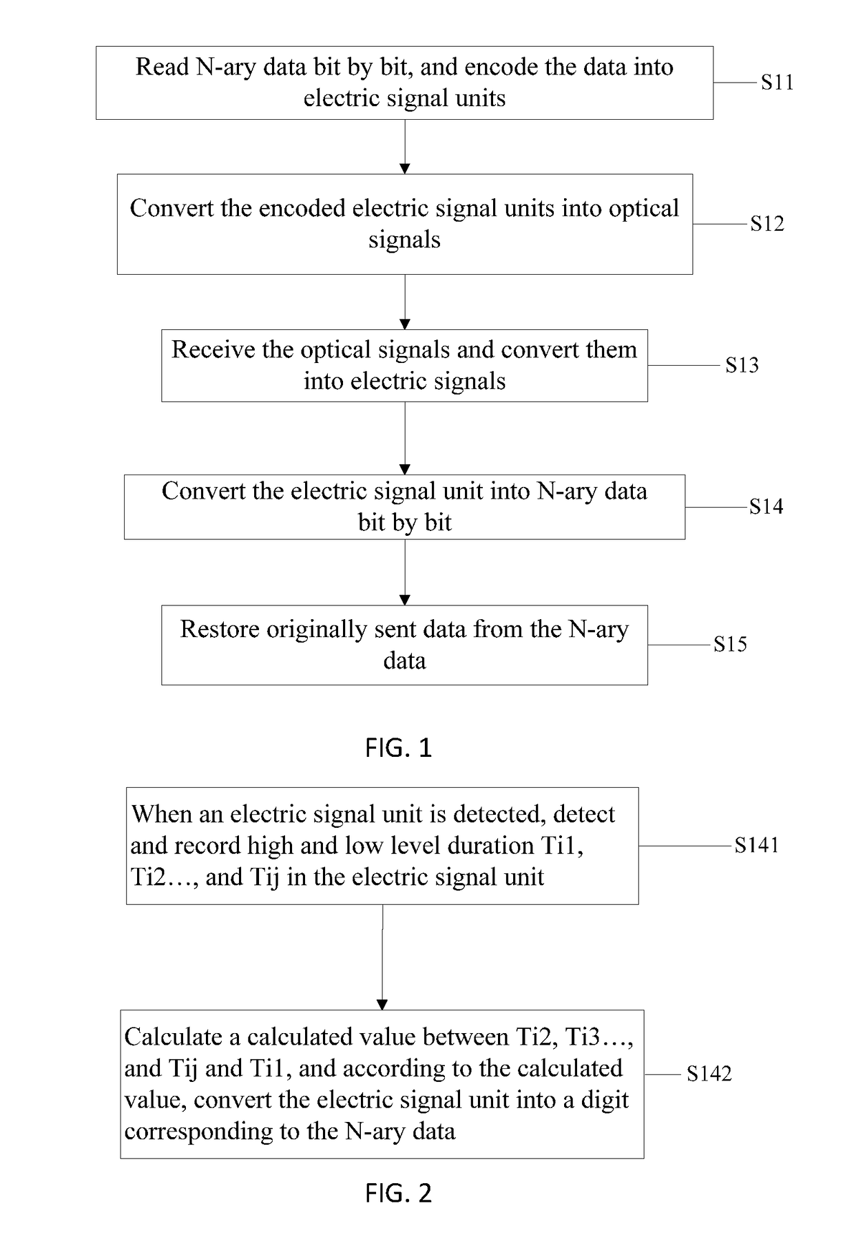
[0038]Therefore, in encoding, an encoding flowchart is shown in FIG. 1. In this embodiment, stroboscopic visible light emitted by a flash of a mobile phone and stroboscopic visible light emitted by a photonic client can be encoded, and...

embodiment 2

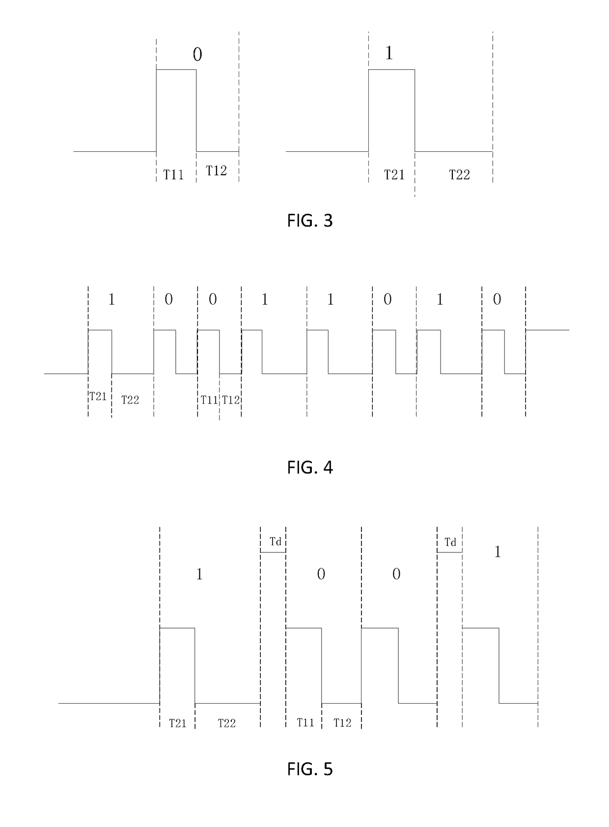
[0068]Based on the encoding method in Embodiment 1, this embodiment provides another calculation relationship of high and low level duration Ti1, Ti2 . . . , Tij in different electric signal units. Specifically, the calculation relationship is a difference operation between Ti2, Ti3 . . . , and Tij and Ti1. Specifically, binary data is used as an example. Binary data 0 is encoded into a first electric signal unit, and high level duration and low level duration in the first electric signal unit are T11 and T12 respectively. Binary data 1 is encoded into a second electric signal unit, and high level duration and low level duration in the second electric signal unit are T21 and T22 respectively. In this embodiment, a relationship between T12 and T11 and a relationship between T22 and T21 are: A difference between T12 and T11 is less than or equal to a third predetermined value (|T12−T11|T0), where the third predetermined value is preset decision duration T0. The setting of T0 needs to ...

embodiment 3

[0079]Based on Embodiment 1 and Embodiment 2, this embodiment further uses N=3 as an example to describe an encoding and decoding method provided in the present disclosure. A flowchart of the method is shown in FIG. 6, and the method includes the following detailed steps.

[0080]S31. Read ternary data bit by bit, and encode the data into electric signal units.

[0081]The ternary data is converted into corresponding electric signal units bit by bit. This step includes: encoding each different digit in the ternary data into a different electric signal unit, where different electric signal units are separated by delimiters. As regards the high level and the low level in the electric signal unit in this embodiment, a high level does not come before a low level by default. Instead, a low level may come before a high level. A delimiter between a high level and low level may be a level transition; or high or low level that continues for different duration is used as a characteristic level, and...


PUM


Abstract

The present disclosure discloses methods and devices for an optical signal encoding and decoding. The optical signal encoding method includes: reading N-ary data bit by bit, and encoding the data into electric signal units: encoding each different digit in the N-ary data into a different electric signal unit, where high level duration and low level duration in the electric signal unit are Ti1, Ti2, . . . , and Tij respectively, i, j, and N are natural numbers, and the different electric signal units are separated by delimiters; and combining the electric signal units corresponding to the N-ary data into a drive signal, where the drive signal is used for being output in a light form. Instable flashing of emitted light of a terminal device is overcome effectively, and information transmission reliability is further improved.

Description

CROSS REFERENCE TO RELATED APPLICATIONS[0001]This application is a continuation of PCT Application No. PCT / CN2015 / 086826 filed on Aug. 13, 2015, which claims priority to Chinese Patent Application No. 201410454019.3 of Sep. 5, 2014 and Chinese Patent Application No. 201410452192.X of Sep. 5, 2014, all of which are incorporated herein by reference.TECHNICAL FIELD[0002]The present disclosure relates to the field of visible light communications, and in particular, to methods and devices for optical signal encoding and decoding.BACKGROUND[0003]A wireless light communications technology is also called visible light communication, which uses frequent flash of an LED light source to communicate. Presence of light represents 1, and absence of light represents 0, and a transmission rate in the visible light communication is up to 1000 Mbps per second. The wireless light communication performs data transmission by using visible light. Compared with a microwave technology, the wireless light c...

Claims


Application Information

Patent Timeline
IPC IPC(8): H04B10/116
CPCH04B10/116H04B10/524H04L25/4902H04B10/516H04B10/612H04B10/114
Inventor LIU, RUOPENGWANG, XUDONGXU, WEICHENGFAN, LINYONG
Owner KUANG CHI INTELLIGENT PHOTONIC TECH
Why Eureka
Try Eureka