Storage apparatus and data processing method thereof, and storage system
a storage apparatus and data processing technology, applied in the direction of redundant data error correction, input/output to record carriers, instruments, etc., can solve the problem that the attribute of ssd loading commands in multiple queues and parallel execution of commands cannot be leveraged
- Summary
- Abstract
- Description
- Claims
- Application Information
AI Technical Summary
Benefits of technology
Problems solved by technology
Method used
Image
Examples
embodiment 1
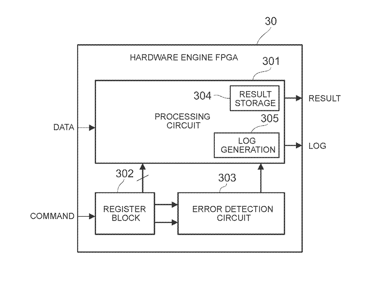
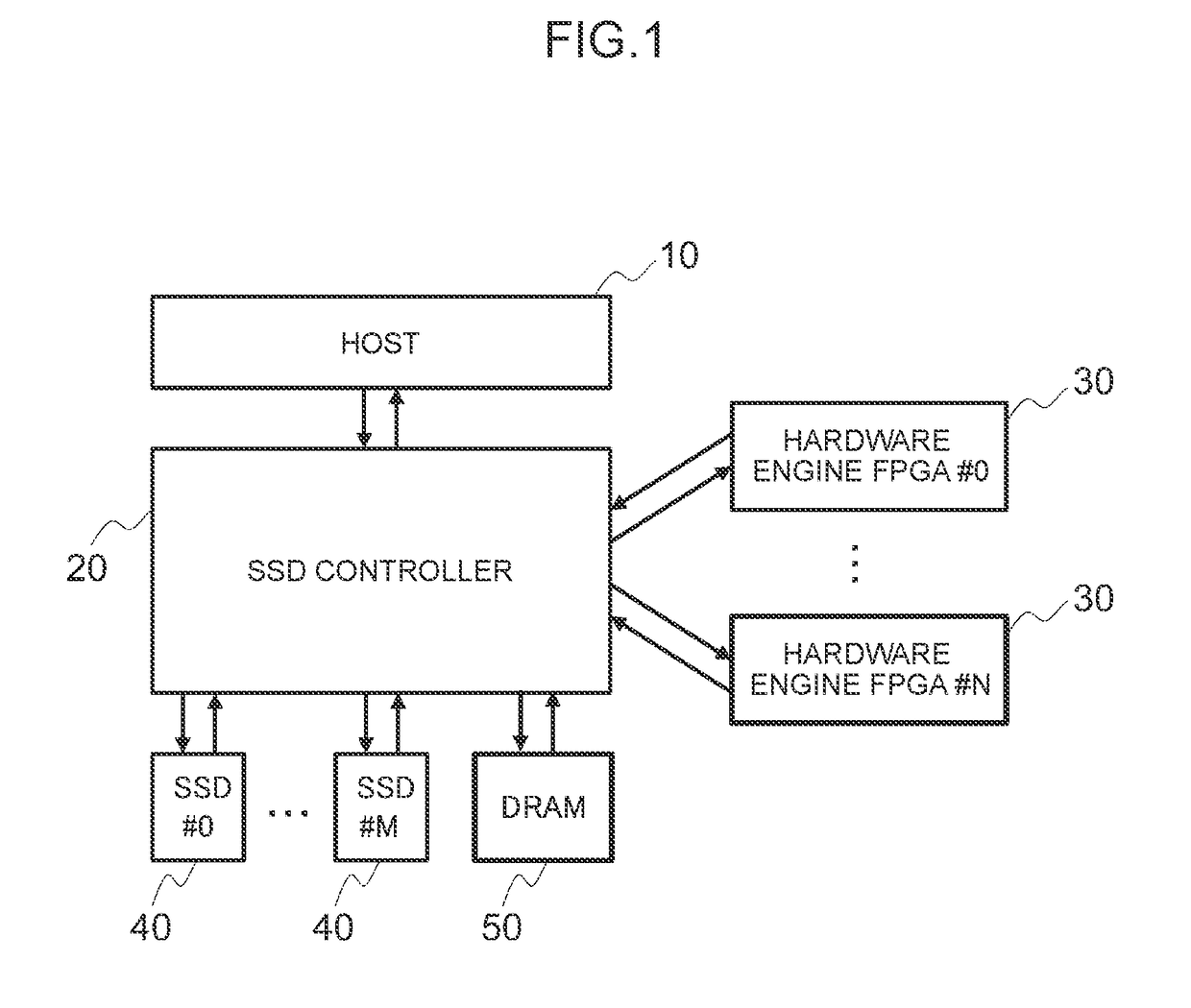
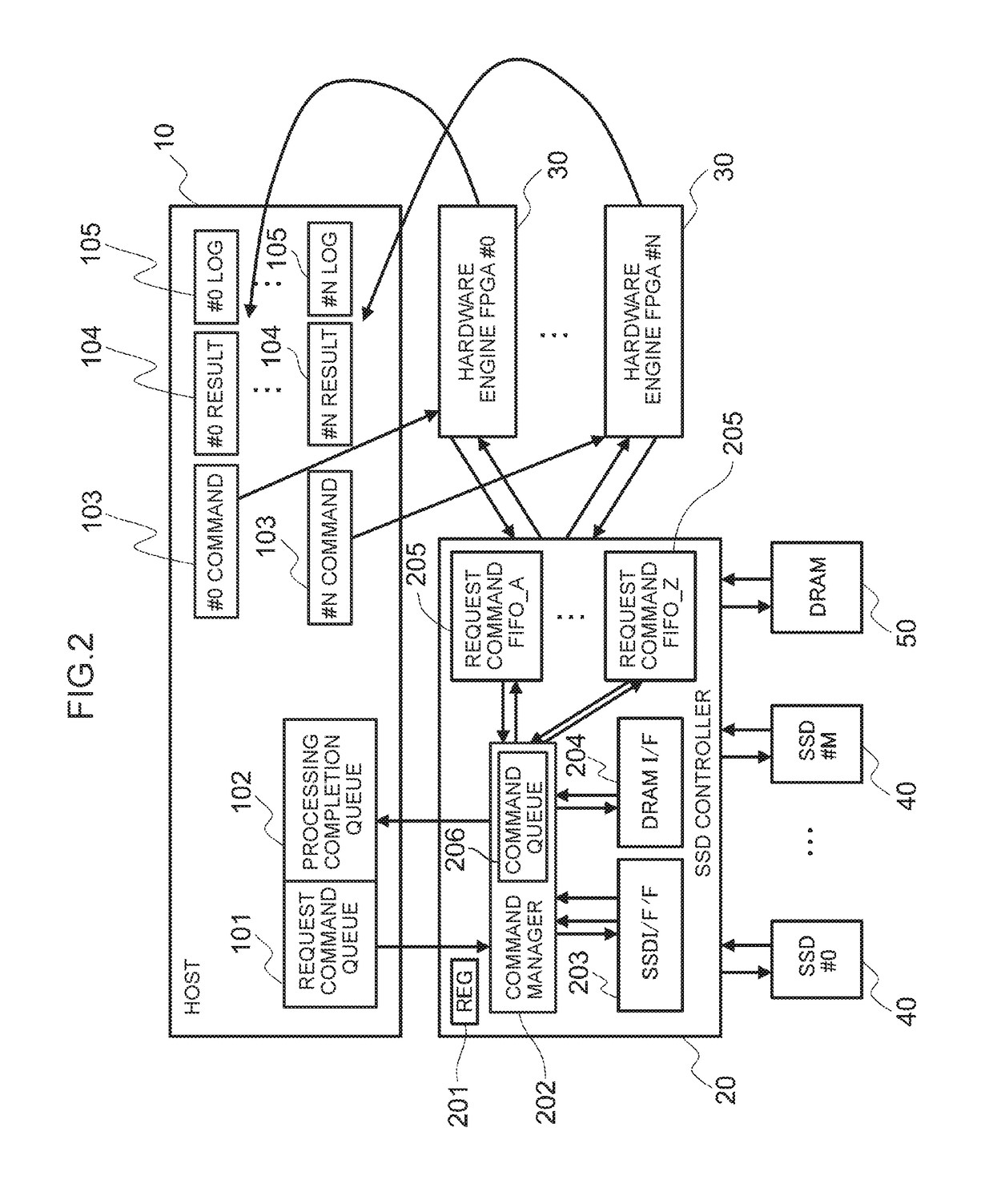
[0036]FIG. 1 is a basic configuration diagram showing the first embodiment of the storage system according to the present invention. In FIG. 1, the storage system includes, as a storage system comprising an add-on adding mechanism, a host (host computer) 10, an SSD (Solid State Drive) controller 20, a plurality of (#0 to #N) hardware engines 30, a plurality of (#0 to #M) SSDs 40, and a DRAM (Dynamic Random Access Memory) 50, and the respective components are mutually connected via a network or a bus. Note that the SSD controller 20, the respective hardware engines 30, the respective SSDs 40 and the DRAM 50 are configured as storage apparatuses.
[0037]The host 10 is a computer device comprising a CPU (Central Processing Unit), a memory, an I / O interface and other information processing resources, and is configured, for instance, from a personal computer, a workstation, or a mainframe. The host 10 separately manages a request command, such as an NVMe command, which is defined according...
embodiment 2
[0076]In this embodiment, when there are three hardware engines 30 having the same function, the SSD controller 20 manages the request commands 140 with one request command FIFO 205.
[0077]FIG. 6 is a configuration diagram showing the second embodiment of the storage system according to the present invention. In FIG. 6, the storage system according to this embodiment has three (#0 to #2) hardware engines 30 having the same function as the hardware engines.
[0078]Here, in correspondence to three hardware engines 30, the host 10 is provided with #0 to #2 command storage areas 103, #0 to #2 result areas 104, and #0 to #2 log areas 105, and the SSD controller 20 is provided with one request command FIFO 205 for managing the three hardware engines 30 having the same function, but the remaining configuration is the same as Embodiment 1. Information of #0 to #2 is added to the end of the address of each command storage area 103 and each result area 104 and each log area 105, and managed by b...
embodiment 3
[0091]In this embodiment, when there is a hardware engine 30 having two types of functions, the SSD controller 20 manages the request commands 140 with two types of request command FIFOs 205.
[0092]FIG. 9 is a configuration diagram showing a third embodiment of the storage system according to the present invention. In FIG. 9, the storage system according to this embodiment has five (#0 to #4) hardware engines 30 having two types of functions (#A, #B) as the hardware engines.
[0093]Here, in correspondence to five hardware engines 30, the host 10 is provided with #0 to #4 command storage areas 103, #0 to #4 result areas 104, and #0 to #4 log areas 105, and the SSD controller 20 is provided with two types (#A, #B) of request command FIFOs 205 for managing the request command 140 to the five hardware engines 30 having two types of functions (#A, #B), but the remaining configuration is the same as Embodiment 1. Note that information of #0 to #4 is added to the end of the address of each co...
PUM
 Abstract
Description
Claims
Application Information
 - R&D
- Intellectual Property
- Life Sciences
- Materials
- Tech Scout
- Unparalleled Data Quality
- Higher Quality Content
- 60% Fewer Hallucinations
Browse by: Latest US Patents, China's latest patents, Technical Efficacy Thesaurus, Application Domain, Technology Topic, Popular Technical Reports.
© 2025 PatSnap. All rights reserved.Legal|Privacy policy|Modern Slavery Act Transparency Statement|Sitemap|About US| Contact US: help@patsnap.com


