Device for the contact-free transfer of electrical energy into a moving system of a shifting device

a technology of electrical energy and shifting device, which is applied in the direction of circuit arrangement, electrical equipment, inductance, etc., can solve the problems of disadvantageous effect on the dynamics of the shifting system and often perceived disadvantage of the cable loom, and achieve the effect of reducing the energy transfer capability and reducing the magnetic flux density

Active Publication Date: 2017-07-06
SCHNEEBERGER HLDG AG
View PDF8 Cites 23 Cited by
  • Summary
  • Abstract
  • Description
  • Claims
  • Application Information

AI Technical Summary

Benefits of technology

[0012]According to an advantageous embodiment, provision is made for the secondary core to comprise at least one secondary core gap, which is embodied along the entire longitudinal extension of the secondary core. In the case of a device, which is further developed in such a way, the advantageous effects of primary core gap and secondary core gap complement one another with respect to the eddy current losses in the primary core and in the secondary core.
[0013]According to a further advantageous embodiment, provision is made for the at least one primary core gap and / or the at least one secondary core gap to be less than or equal to 0.2 mm, preferably less than or equal to 0.1 mm, along the entire longitudinal extension of the primary core or of the secondary core, respectively.
[0014]The primary coil and / or the secondary coil can furthermore be designed in such a way that they can be operated with an alternating current of up to 50 A. Primary coil and secondary coil can furthermore also be embodied in such a way that they can be operated with an alternating current / alternating voltage frequency of between 100 kHz and 500 kHz, in particular between 200 kHz and 400 kHz.
[0015]In the case of an operating frequency of between 100 kHz and 500 kHz, the primary core gap and / or the secondary core gap can be utilized in an advantageous manner, even though the magnetic flux density is reduced. The magnetic flux density of the arrangement lies in the range of 0.05 T, for example.
[0016]According to a further advantageous embodiment, provision is made for the primary core to exclusively comprise a magnetically conducting material or exclusively magnetically conducting materials; this differs from the prior art, where the primary core is segmented and is interrupted by filling elements of non-magnetically conducting material.
[0017]It was recognized according to the invention that, in the case of the device known from the prior art, a very large portion of the secondary core volume remains effectively unused for the embodiment of the magnetic circuit between primary and secondary side, in accordance with the dimension of the non-magnetic filling segment along the shifting direction. The magnetic coupling between primary and secondary side and thus the energy transfer capability is reduced hereby as a whole in a disadvantageous manner. On the other hand, the moved mass is increased unnecessarily because of the unused portion of the secondary core volume, which, in turn, can have a disadvantageous effect on the dynamics of the shifting system.

Problems solved by technology

However, such a cable loom is often perceived to be disadvantageous, because it can transfer mechanical interferences, for example vibrations, from the stationary system into the second system, which is to be positioned accurately, for example in the case of highly accurate positioning applications, for instance in the field of semiconductor technology.
Due to the segmented design of the primary core, the device as a whole is limited with regard to the transferable energy in the case of the solution known from JP 6 204 043 A. In addition, the required minimum length of the secondary core along the shifting direction increases the moved total mass of the second system, which, in turn, can have a disadvantageous effect on the dynamics of the shifting system.

Method used


Image

  • Device for the contact-free transfer of electrical energy into a moving system of a shifting device
  • Device for the contact-free transfer of electrical energy into a moving system of a shifting device
  • Device for the contact-free transfer of electrical energy into a moving system of a shifting device

Examples


Embodiment Construction

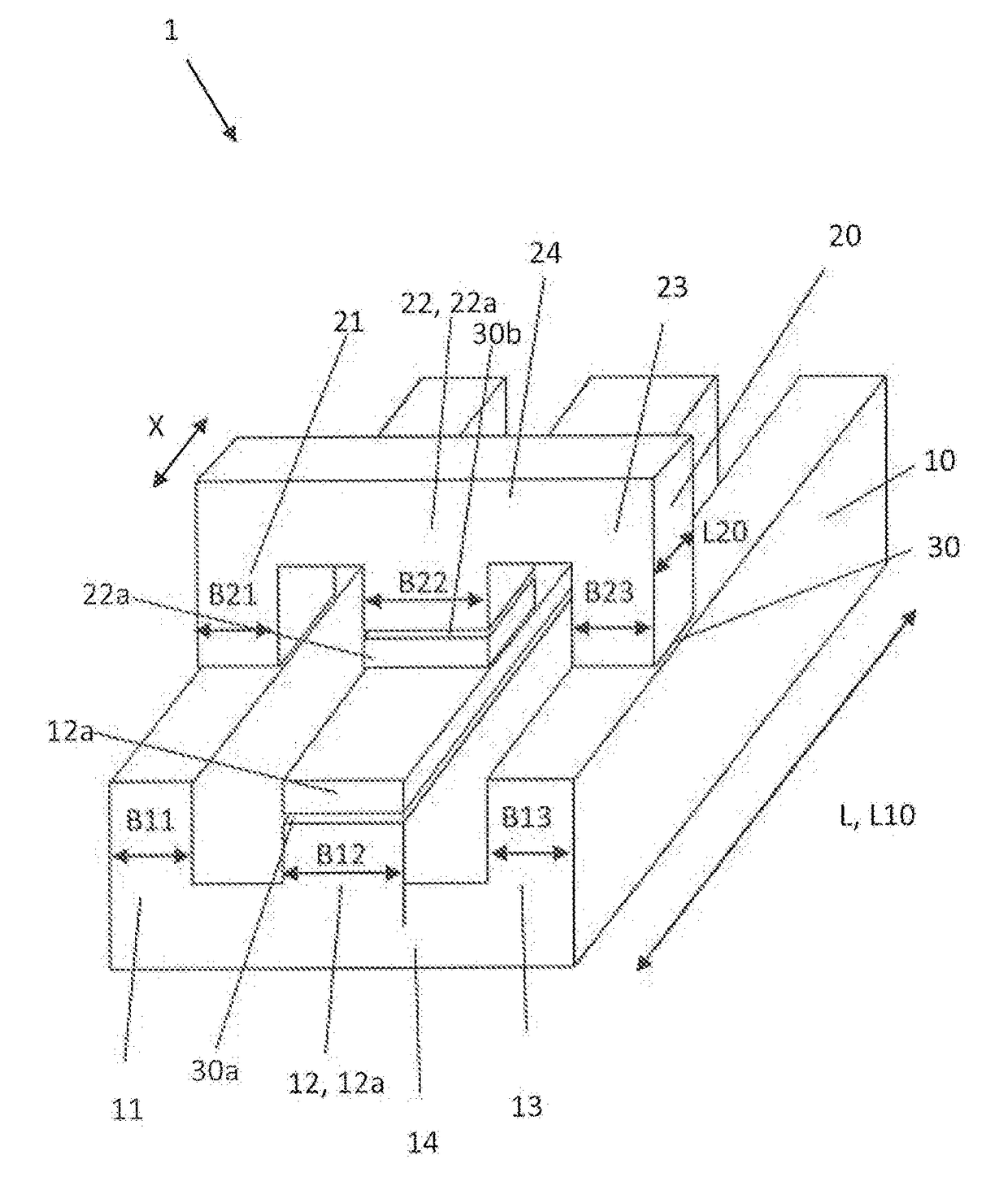
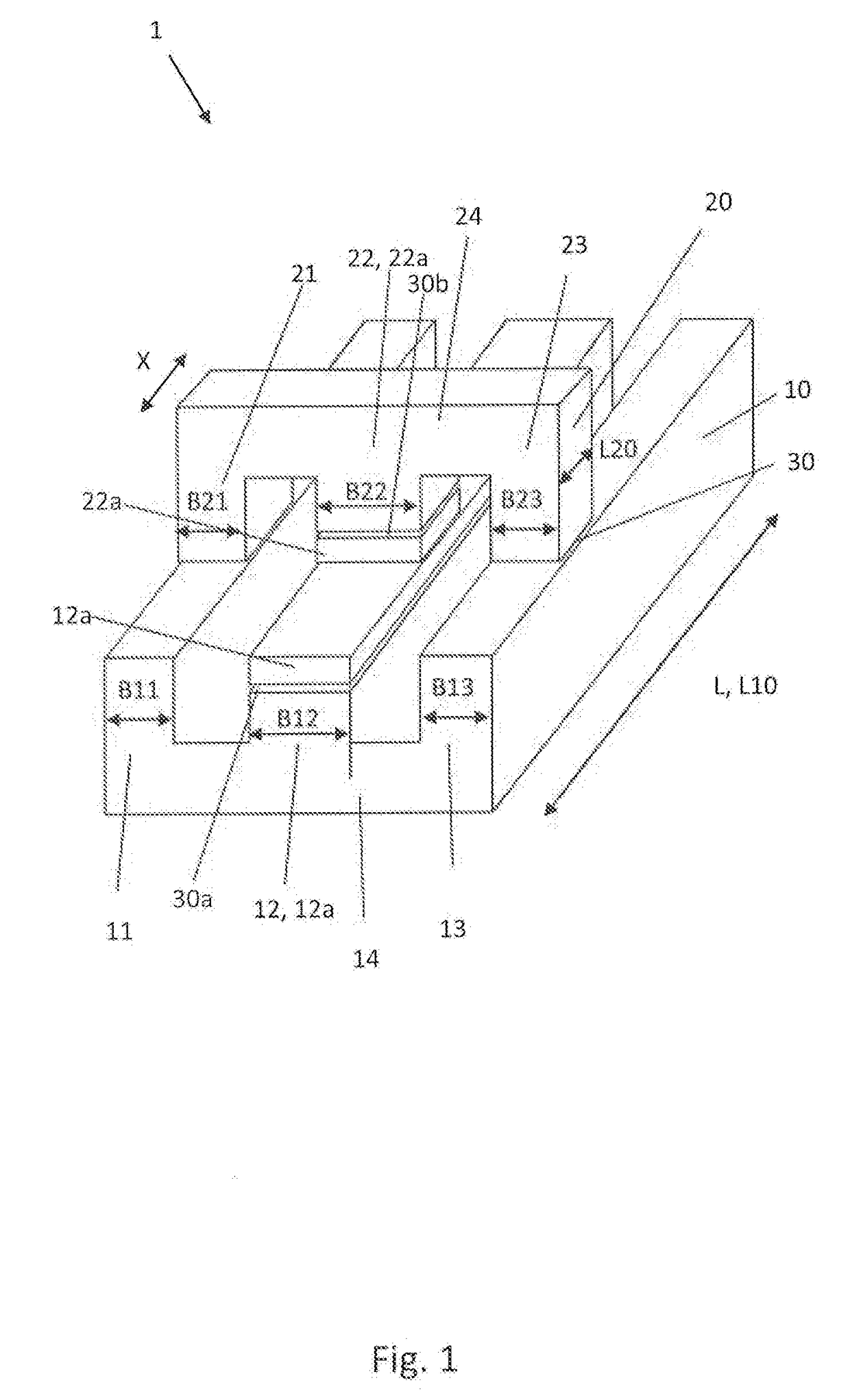
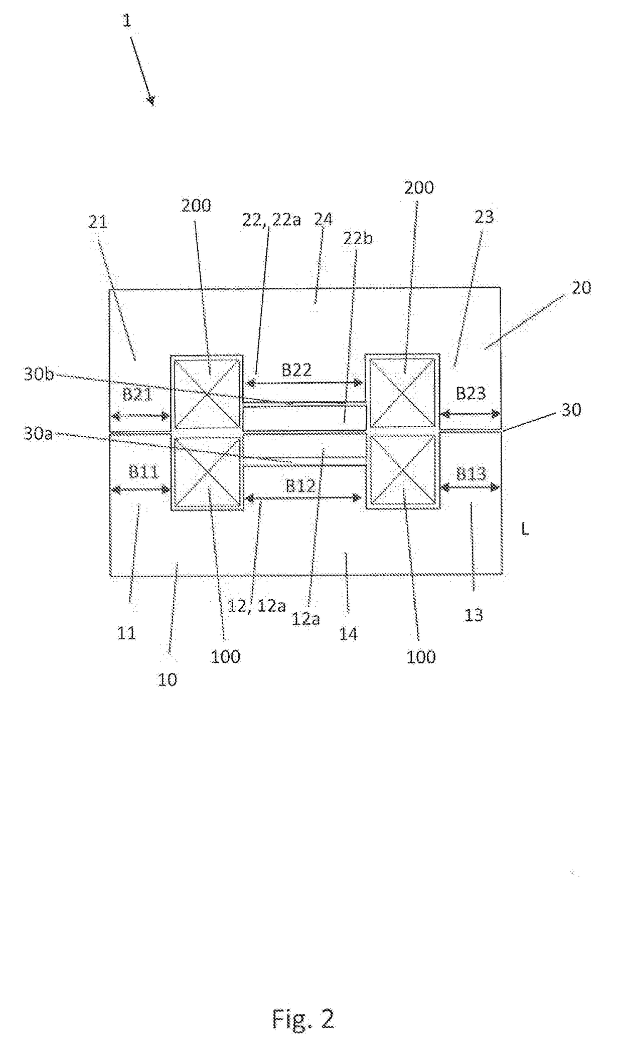
[0036]FIGS. 1 and 2 show a possible exemplary embodiment of an energy transfer device 1 according to the invention, which is embodied to inductively transfer electrical energy from a first, preferably stationary system of a shifting device (not illustrated here) into a second system of the shifting device, which is moved to this end, in a contact-free or cable-free manner, respectively. The exemplary embodiment at hand shows a linear guided energy transfer device 1, which is specifically embodied to transfer electrical energy from the stationary into the moving system of a linear guide device.

[0037]As can be gathered from FIGS. 1 and 2, the energy transfer device 1 shown herein consists of a stationary part and of a movable part, namely of a primary core 10, which is stationary to the first system of the linear guide device, and a secondary core 20, which can be moved relative thereto and which is assigned to the second system of the linear guide device. Concretely, the secondary co...


PUM

PropertyMeasurementUnit
alternating current/alternating voltage frequencyaaaaaaaaaa

Abstract

The present invention relates to a device for the contact-free inductive transfer of electrical energy from a first, preferably stationary system of a shifting device into a second system of the shifting device, which can be moved relative to the first system, comprising a magnetic circuit of a primary core, which is assigned to the first system and onto which a primary coil is wound, and a secondary core, which is assigned to the second system and onto which a secondary coil is wound. The secondary core is arranged so as to be capable of being shifted relative to the primary core along a shifting path, which preferably runs parallel to a shifting path of the shifting device. The primary core extends at least along the entire length of the shifting path. According to the invention, provision is made for the primary core to comprise at least one primary core gap, which is embodied along the entire longitudinal extension of the primary core. The invention further relates to a shifting device, in particular a linear shifting device, comprising such an energy transfer device as well as to a method for operating such a device.

Description

FIELD OF THE INVENTION[0001]The present invention relates to a device for the contact-free, inductive transfer of electrical energy from a first, preferably stationary system of a shifting device into a second system of the shifting device, which can be moved with respect to the first system. The invention further relates to a (linear) shifting device comprising such an energy transfer device as well as to a method for operating the energy transfer device.BACKGROUND[0002]On principle, shifting devices, in particular one-dimensional or multi-dimensional or uniaxial or multiaxial linear shifting devices, respectively, for instance so-called X or XY shifting tables, consist of one or a plurality of uniaxial (linear) guide systems, respectively, which provide for the sometimes highly accurate moving and positioning of an object in one or a plurality of directions. For example, a very simple variant of a one-dimensional or uniaxial shifting device, respectively, consists of a guide rail,...

Claims


Application Information

Patent Timeline
Patent Type & Authority Applications(United States)
IPC IPC(8): H01F38/14H01F27/24H01F21/06H02J50/10
CPCH01F38/14H02J50/10H01F2038/143H01F21/06H01F27/24H01F3/10H01F3/14
Inventor VIX, MARTIN
Owner SCHNEEBERGER HLDG AG
Why Eureka
Try Eureka