Photovoltaic With Improved Visibility and Method for Manufacturing Thereof

a technology of photovoltaic and manufacturing method, which is applied in the direction of photovoltaic supports, climate sustainability, sustainable buildings, etc., can solve the problems of inability to secure visibility, increase manufacturing cost, and the efficiency of thin-film photovoltaics is slightly lower than that of substrate-type photovoltaics, so as to prevent the reduction of visibility and improve the efficiency of conversion of optical to electric energy

Inactive Publication Date: 2017-07-06
JUSUNG ENG
View PDF14 Cites 8 Cited by
  • Summary
  • Abstract
  • Description
  • Claims
  • Application Information

AI Technical Summary

Benefits of technology

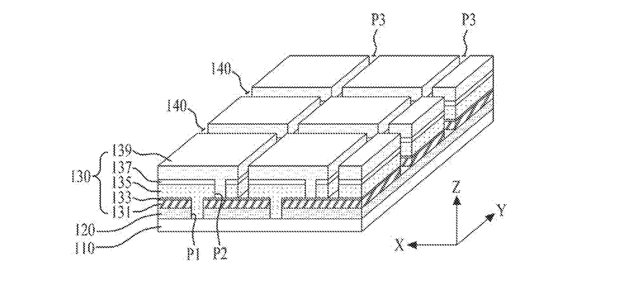
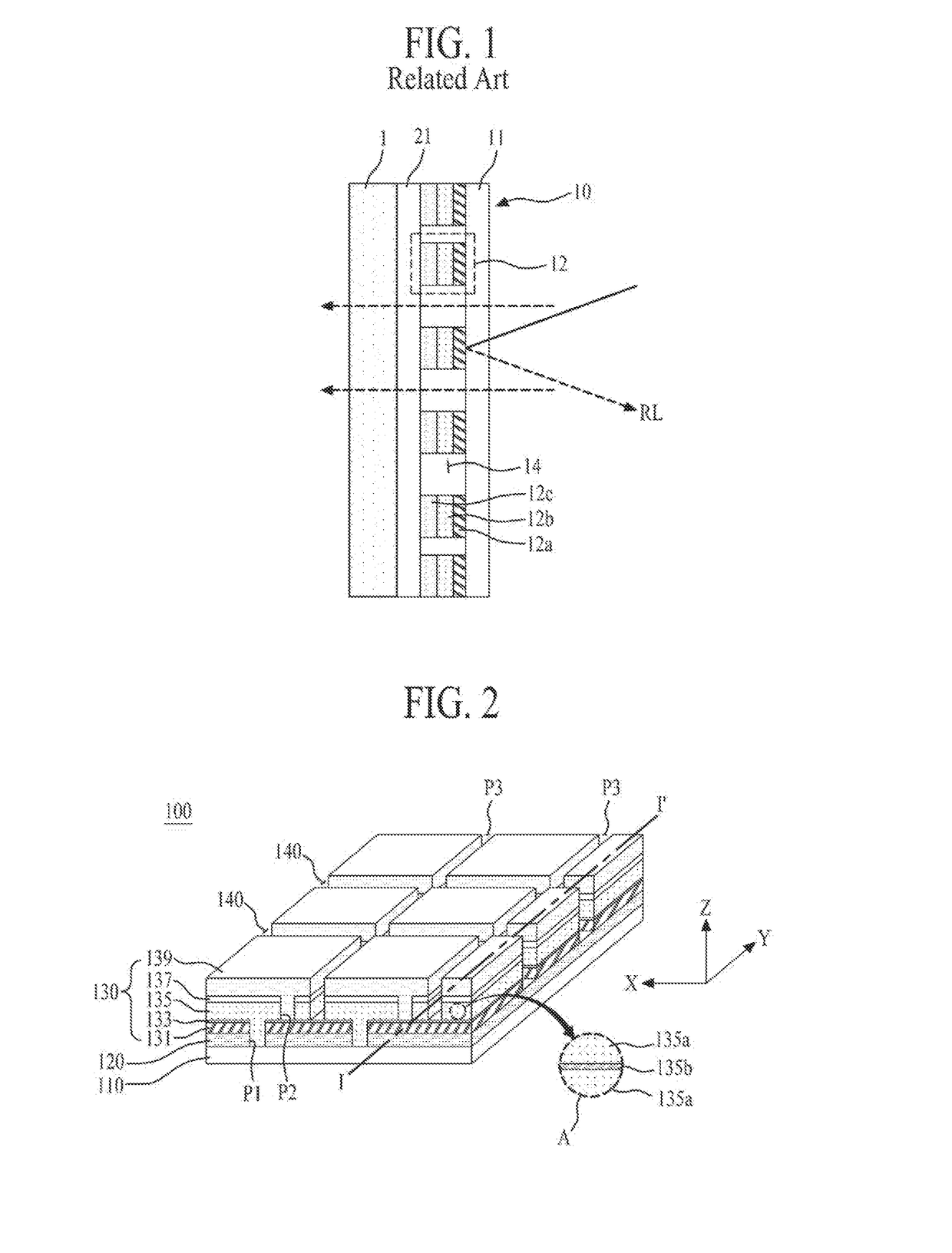
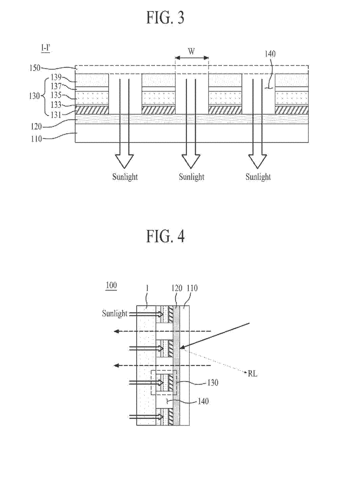
[0020]As described above, according to the embodiments of the present invention, since the photovoltaic cells which are adjacent to each other with the light transmitting part (or the separation part) therebetween are connected to the first electrode through the connection layer (or the transparent electrode) which is formed to overlap the light transmitting part, a visibility of the photovoltaic is secured through the light transmitting part, and optical-to-electric conversion efficiency can be improved.
[0021]Moreover, according to the embodiments of the present invention, since the anti-reflection layer (or the transparent electrode) is formed between the transparent substrate and the first electrode formed of a metal material, visibility can be prevented from being reduced due to a light reflection of a metal electrode when viewing the outside from the inside.

Problems solved by technology

However, the substrate-type photovoltaics have a limitation in minimizing a thickness in a process, and since the substrate-type photovoltaics use a high-priced semiconductor substrate, the manufacturing cost increases.
On the other hand, the thin-film photovoltaics have slightly lower efficiency than the substrate-type photovoltaics.
However, in the related art window-substituting photovoltaic, when viewing the outside from the inside, visibility cannot be secured due to reflection light RL caused by a surface reflection of the rear electrode 12a formed of a metal material.

Method used


Image

  • Photovoltaic With Improved Visibility and Method for Manufacturing Thereof
  • Photovoltaic With Improved Visibility and Method for Manufacturing Thereof
  • Photovoltaic With Improved Visibility and Method for Manufacturing Thereof

Examples


Embodiment Construction

[0027]The terms described in the specification should be understood as follows. It will be further understood that the terms “comprises”, “comprising,”, “has”, “having”, “includes” and / or “including”, when used herein, specify the presence of stated features, integers, steps, operations, elements, and / or components, but do not preclude the presence or addition of one or more other features, integers, steps, operations, elements, components, and / or groups thereof. The term “at least one” should be understood as including any and all combinations of one or more of the associated listed items. For example, the meaning of “at least one of a first item, a second item, and a third item” denotes the combination of all items proposed from two or more of the first item, the second item, and the third item as well as the first item, the second item, or the third item. The term “on” should be construed as including a case where one element is formed at a top of another element and moreover a c...


PUM


Abstract

Disclosed are a photovoltaic with improved visibility, which can improve optical-to-electric conversion efficiency and can be applied to a window of a building or a view window of a moving means such as a vehicle, and a method of manufacturing the same. The photovoltaic includes a transparent substrate, a transparent electrode formed on one surface of the transparent substrate, a plurality of photovoltaic cells configured to each include a first electrode formed on the transparent electrode, an optical-to-electric conversion part formed on the first electrode, and a second electrode formed on the optical-to-electric conversion part, and a separation part provided between adjacent photovoltaic cells. The separation part exposes the transparent electrode to incident sunlight.

Description

TECHNICAL FIELD[0001]The present invention relates to a thin-film photovoltaic, and more particularly, to a photovoltaic with improved visibility, which can be applied to a window of a building or a view window of a moving means such as a vehicle, and a method of manufacturing the same.BACKGROUND ART[0002]Photovoltaics are apparatuses that convert light energy into electrical energy by using the properties of a semiconductor. That is, the photovoltaics have a P-N junction structure in which a positive (P)-type semiconductor is joined to a negative (N)-type semiconductor. The photovoltaics produce power with the following principle. When sunlight is incident on a photovoltaic having the P-N junction structure, a hole (+) and an electron (−) are generated in a semiconductor by energy of the incident sunlight. At this time, due to an electric field which is generated based on P-N junction, the hole (+) moves toward a P-type semiconductor, and the electron (−) moves toward an N-type sem...

Claims


Application Information

Patent Timeline
Patent Type & Authority Applications(United States)
IPC IPC(8): H01L31/0468H02S20/22H01L31/0216H02S40/42H01L31/0224H01L31/05
CPCH01L31/0468H01L31/022475H01L31/0512H02S20/22H01L31/022483H02S40/42H01L31/02168H01L31/046Y02E10/50Y02B10/10
Inventor KIM, YONG HYUNPARK, CHANG KYUNPYUN, SEUNG-CHEOLHONG, YONG KYU
Owner JUSUNG ENG
Why Eureka
Try Eureka