Motion sensor device and use thereof

Active Publication Date: 2017-07-06
STEINEL
View PDF0 Cites 2 Cited by
  • Summary
  • Abstract
  • Description
  • Claims
  • Application Information

AI Technical Summary

Benefits of technology

[0006]The present invention therefore is based on the objective of realizing a motion sensor device such that it is more user friendly, can be easily handled and, in particular, arbitrarily and flexibly configured by untrained or easily trainable users, wherein it should al

Problems solved by technology

However, devices of this type, which are based on the infrared principle, also have certain disadvantages; first of all, an effective detection region, i.e. a region defined by the maximum distance of a detection object with a certain minimum size to be reliably detected, is limited due to the principle used.
In addition, infrared-based sensors can be affected by environmental influences such as, e.g., changes in the temperature and/or light conditions and therefore cause potentially undesirable false activations.
However, this high-frequency technology is—due to the principle used—also associated with certain disadvantages; a detector sensitivity (and therefore also a motion detection sensitivity) is dependent on the (moving) direction, in which the detection object moves relative to the sensor.
In addition, the difference between a relatively small detection object moving in the vicinity of the sensor and a relatively large object moving at a greater distance from the sensor (and potentially even outside a desired detection region)

Method used


Image

  • Motion sensor device and use thereof
  • Motion sensor device and use thereof
  • Motion sensor device and use thereof

Examples


Embodiment Construction

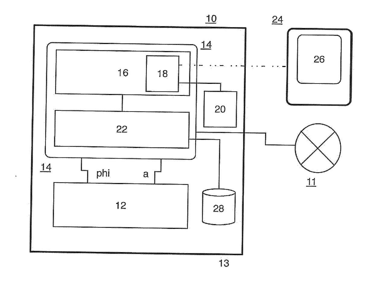
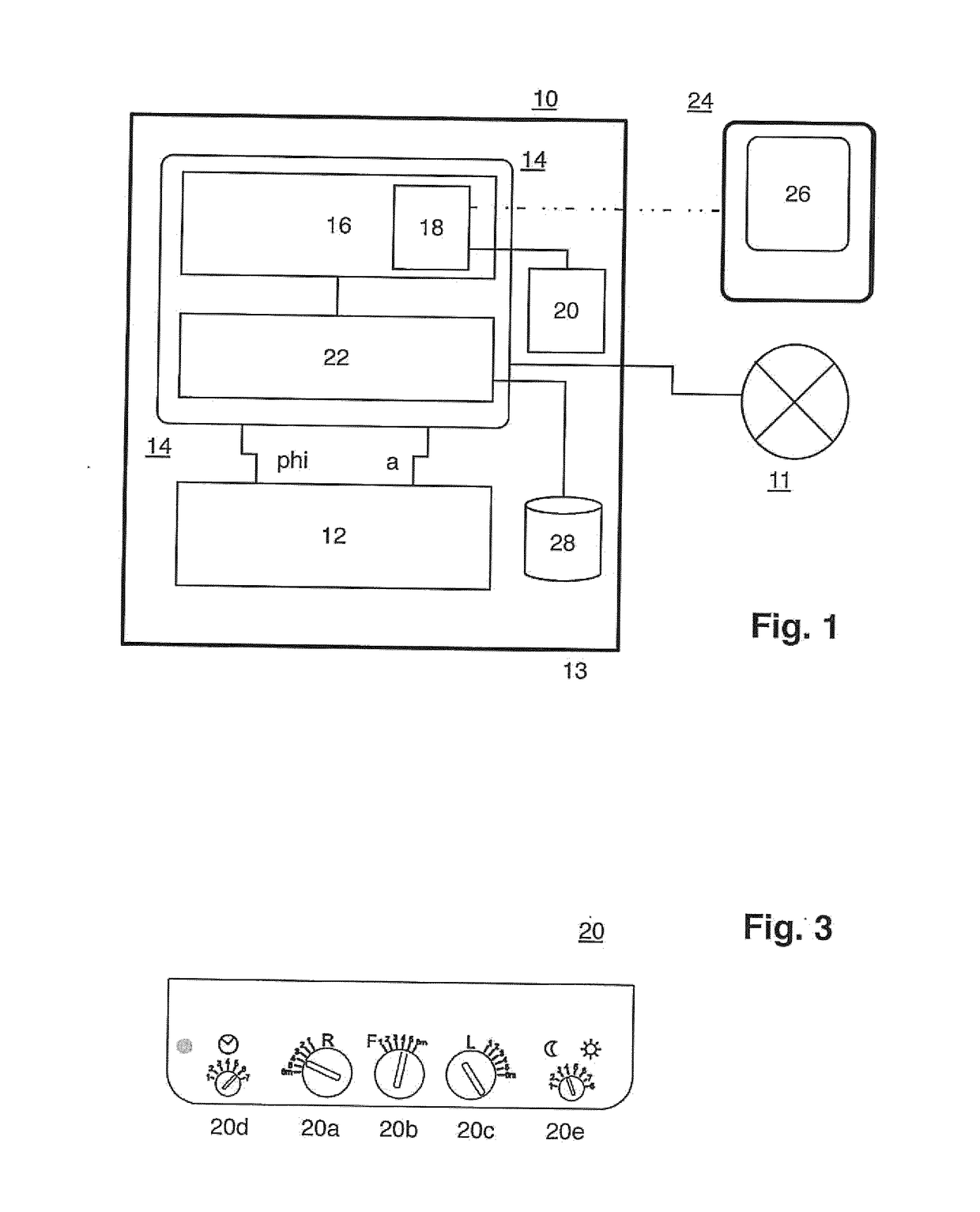
[0023]FIG. 1 shows a first preferred exemplary embodiment of a motion sensor device according to the present invention in the form of a schematic block diagram. Detector means 12 are provided in a housing, which is indicated with the border line 10 and suitably mounted on a wall, a ceiling or the like, and realized in the form of a high-frequency motion sensor device; detector means of this type in the form of high-frequency motion sensors are disclosed in DE 10 2012 103 177 A1 by the applicant, which with respect to the constructive realization of such a motion sensor device including the realization of the functional components according to FIG. 1 of this publication, the high-frequency hardware according to FIG. 2 of this publication and the signal processing functionality according to FIGS. 3, 4 of this publication, as well as the corresponding portions of the description, is incorporated into the disclosure of the present application by reference. Detector means designed in thi...


PUM


Abstract

A motion sensor device for detecting a detection object in a detection region, with detector means (12) which are arranged in a sensor housing (10) and designed for detecting motions of the detection object, as well as for generating an electronic distance signal (a) and angle signal (phi) corresponding to the detection object, wherein the distance signal (a) corresponds to an instantaneous distance of the detection object from the sensor housing (13) and the angle signal corresponds to an instantaneous position angle (phi) of the detection object in the form of an azimuth angle in a plane of motion of the detection object extending parallel to the ground surface in the installed state of the motion sensor device on a wall and signal processing and control means (14) connected downstream of the detector means are designed for activating a device (11) to be connected downstream of the motion sensor device in dependence on the distance signal and the angle signal, and wherein the signal processing and control means feature detection region determining means (16) with an interface unit (18; 20), which can be adjusted, configured and/or actuated by a user and serves for at least sectionally adjusting and/or defining a boundary of the detection region in the plane of motion, wherein the signal processing and control means feature comparing means (22), which are designed for comparing a distance signal and angle signal generated for a detection object by the detector means with data on a predefined or adjusted boundary of the detection region that can be variably defined and/or adjusted relative to the sensor housing frontally (32) and laterally (30, 34) in the plane of motion, wherein display and/or visualization means (26) are assigned to the interface unit (18) in order to optically display and/or output the boundary.

Description

BACKGROUND OF THE INVENTION[0001]The present invention relates to a motion sensor device. The present invention furthermore relates to the utilization of such a motion sensor device within a wall or ceiling light.[0002]Motion detection sensors in the form of various detection technologies and corresponding technical principles are known from the prior art, wherein a common and frequent application is the use of such a motion detection sensor for activating a light. For example, it is common practice to utilize so-called PIR (passive infrared) sensors for the motion detection in interior and exterior regions (e.g. referred to a building, on which a corresponding motion sensor device is installed either by itself or in connection with a lighting unit) and to thereby control a lighting system, wherein these sensors generate a detection signal based on detected infrared radiation in the detection region (more precisely: infrared radiation in the map of the detection region, which change...

Claims


Application Information

Patent Timeline
IPC IPC(8): H04N5/232G06T7/20G06K9/00H04N5/14
CPCH04N5/23212H04N5/144H04N5/23296H04N2005/2255G06K9/00335G06K9/00624G06T7/20G01S7/2813G01S13/42G01S13/88H05B47/115Y02B20/40G06V40/20H04N23/69H04N23/555
Inventor MOELLER, THOMASCAPALINI, RICHARD
Owner STEINEL
Why Eureka
Try Eureka