System and Method for Fusing Outputs of Sensors Having Different Resolutions

a technology of sensor output and output, applied in the field of sensing systems and methods, can solve the problems of depth sensors such as lidar sensors that do not have sufficient resolution for practical applications, sensors are prone to lose calibration, and offline calibration is not possible or practical for some applications, so as to improve the final output and boost the performance of the other.

Active Publication Date: 2017-07-13
MITSUBISHI ELECTRIC RES LAB INC
View PDF2 Cites 35 Cited by
  • Summary
  • Abstract
  • Description
  • Claims
  • Application Information

AI Technical Summary

Benefits of technology

[0008]Some embodiments of the invention are based on a realization that fusion and calibration are complementary processes and improvements in one can be used to boost the performance of the other. Thus, a joint calibration and fusion method can improve the final output. In contrast to existing approaches, which typically address either calibration or fusion, but not both, the joint processing works towards a common objective: improving the final output of the sensor fusion as a function of calibration parameters.

Problems solved by technology

Some depth sensors, such as LIDAR sensor, do not have sufficient resolution for practical applications.
However, performing the offline calibration is not possible or practical for some applications.
This problem is especially apparent when the sensors are installed at the moving vehicle.
This is because such sensors are prone to lose the calibration due to potential roughness of the road conditions, and the calibrations needs to be performed online for constantly varying scenes.
However, in some applications, the calibration based on edge matching is inaccurate due to low resolution of the sensor measurements.

Method used


Image

  • System and Method for Fusing Outputs of Sensors Having Different Resolutions
  • System and Method for Fusing Outputs of Sensors Having Different Resolutions
  • System and Method for Fusing Outputs of Sensors Having Different Resolutions

Examples


example embodiments

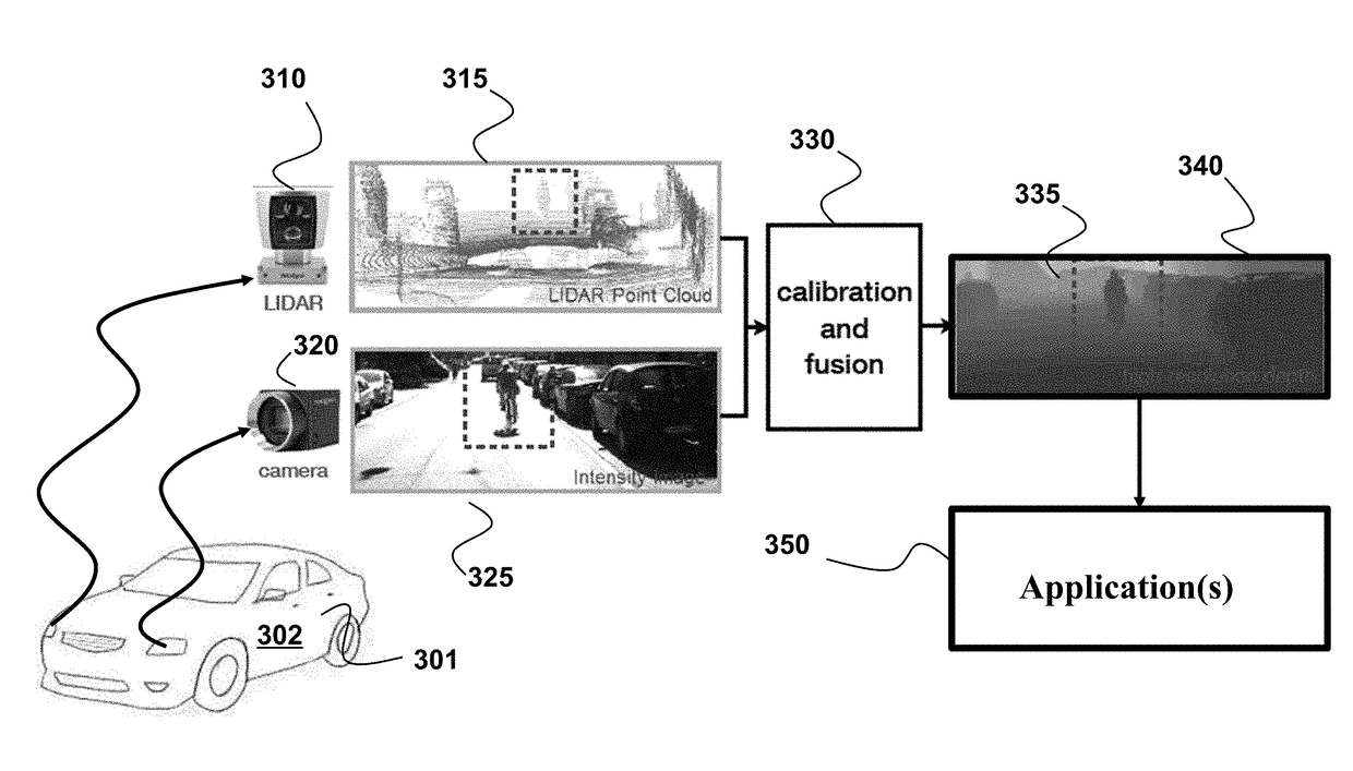
[0052]FIG. 3 shows a schematic of a system according to one embodiment of the invention. The system include a first sensor 310 to measure a scene to produce a first set of measurements of the scene and a second sensor 320 to measure the scene to produce a second set measurements of the scene. For example, the first sensor 310 is a LIDAR and the second sensor 320 is a camera. The LIDAR sensor 310 is the low-resolution first sensor and the camera 320 is the high-resolution second sensor.

[0053]The system also includes a processor 302 to perform jointly a calibration of the first and the second sensors and a fusion of the first and the second set of measurements according to principles employed by various embodiments of the invention. For example, in one embodiment, the first and the second sensors are installed at a vehicle 301 and the processor 302 forms a part of a computational system of the vehicle. Additionally or alternatively, the processor 302 can be the processor of the sensor...


PUM


Abstract

A method for fusing measurements of sensors having different resolutions performs jointly a calibration of the sensors and a fusion of the their measurements to produce calibration parameters defining a geometrical mapping between coordinate systems of the sensors and a fused set of measurements that includes the modality of a sensor with resolution greater than its resolution. The calibration and the fusion are performed jointly to update the calibration parameters and the fused set of measurements in dependence on each other.

Description

FIELD OF THE INVENTION[0001]This invention relates to sensing systems and methods, and more specifically to fusing outputs of sensors having different resolutions.BACKGROUND OF THE INVENTION[0002]Sensor fusion is a process of combining the sensory data derived from different sensors. As an increasing number of sensors and sensor modalities are used to acquire scenes, consolidation or fusion of the sensor data is becoming increasingly important. Sensor fusion exploits the distinct sensor modalities to provide complimentary information about the environment, overcome hardware limitations, or reduce data uncertainty due to each individual sensor. For example, the sensor fusion can increase, i.e., upsample, the resolution on data measured by one sensor using measurements of another sensor. Additionally or alternatively, the sensor fusion can annotate the data measured by one sensor with the measurements of another sensor.[0003]For example, the depth sensing is a technology for measuring...

Claims


Application Information

Patent Timeline
Patent Type & Authority Applications(United States)
IPC IPC(8): G06T7/00G06T3/40H04N5/232G01S13/931G01S17/86G01S17/894G01S17/931
CPCG06T7/0018G06T3/4053G06T7/003H04N5/23232G01S7/4808G01S13/867G06T5/50G06T2207/10024G06T2207/10028G06T2207/20221G01S17/86G01S17/894G06T2207/30261G06V20/58G01S7/4026G01S13/89G01S17/931G01S13/931H04N23/45H04N23/951G06T7/80G06T7/337
Inventor KAMILOV, ULUGBEKCASTORENA, JUANBOUFOUNOS, PETROS
Owner MITSUBISHI ELECTRIC RES LAB INC
Why Eureka
Try Eureka