Determining the Deterioration of Oils Using Fluorescence Rise-Time

Inactive Publication Date: 2017-07-20
SAUDI ARABIAN OIL CO
View PDF0 Cites 8 Cited by
  • Summary
  • Abstract
  • Description
  • Claims
  • Application Information

AI Technical Summary

Benefits of technology

[0008]In some embodiments, the operations include controlling a laser to emit light from a light source into the oil sample to induce fluorescence in the oil sample and receiving, over a time period, measurements of the intensity of the detected fluorescence by a detector at a sample rate to obtain the two or more measurements. In some embodiments, the detector is a photodiode. In some embodiments, the operations include providing, on a display coupled to the viscosity processor, a notification indicating the oil has deteriorated.
[0009]In some embodiments, a portable viscosity determination device is provided. The device includes a housing and a light source disposed in the housing and arranged to emit light into an oil sample contained in a sample container. The oil sample includes a sample of an oil from a machine. The portable viscosity determination device further includes a viscosity processor disposed in the housing and a non-transitory computer-readable memory disposed in the housing, the memory having executable code stored on the memory. The executable code includes a set of instructions that causes a viscosity processor to perform operations including determining a fluorescence rise-time of the oil sample from two or more measurements of fluorescence induced by the light source in the oil sample and determining the viscosity of the oil from the fluorescence rise-time.
[0010]In some embodiments, the operations include comparing the viscosity to a viscosity threshold and determining deterioration of the oil based on the comparison. In some embodiments, the operations include providing, on a display coupled to the viscosity processor, a notification indicating the oil has deteriorated. In some embodiments, the operations include providing a notification, on a display coupled to the viscosity processor if the viscosity deviates from the viscosity threshold by a predetermined amount or a predetermined percentage. In some embodiments, the portable viscosity determination device includes a detector arranged to detect the induced fluorescence. In some embodiments, the detector is arranged at a 90° angel from a surface of the sample container. In some embodiments, the operations include controlling the light source to emit light into the oil sample to induce fluorescence in the oil sample and receiving, over a time period, measurements of the intensity of the induced fluorescence by the detector at a sample rate to obtain the two or more measurements. In some embodiments, the detector is a photodiode. In some embodiments, the portable viscosity determination device includes a filter disposed in the housing and arranged to filter the induced fluorescence before detection of the induced fluorescence by the detector. Additionally, in some embodiments, the portable viscosity determination device includes a lens disposed in the housing a

Problems solved by technology

Lubrication oils, especially those used in gas turbines, may deteriorate while in use due to various factors, such as oxidization due to air exposure, depletion of additives such as anti-oxidants and demulsifiers, and chemical deformation of the oil itself due to high temperatures.
The deterioration of lubrication oils may lead to the creation of insoluble compounds which eventually break off from the oil and become deposited in the machine.
Additionally, some machines, such as gas turb

Method used


Image

  • Determining the Deterioration of Oils Using Fluorescence Rise-Time
  • Determining the Deterioration of Oils Using Fluorescence Rise-Time
  • Determining the Deterioration of Oils Using Fluorescence Rise-Time

Examples


Embodiment Construction

[0021]The present disclosure will now be described more fully with reference to the accompanying drawings, which illustrate embodiments of the disclosure. This disclosure may, however, be embodied in many different forms and should not be construed as limited to the illustrated embodiments set forth in the disclosure. Rather, these embodiments are provided so that this disclosure will be thorough and complete, and will fully convey the scope of the disclosure to those skilled in the art.

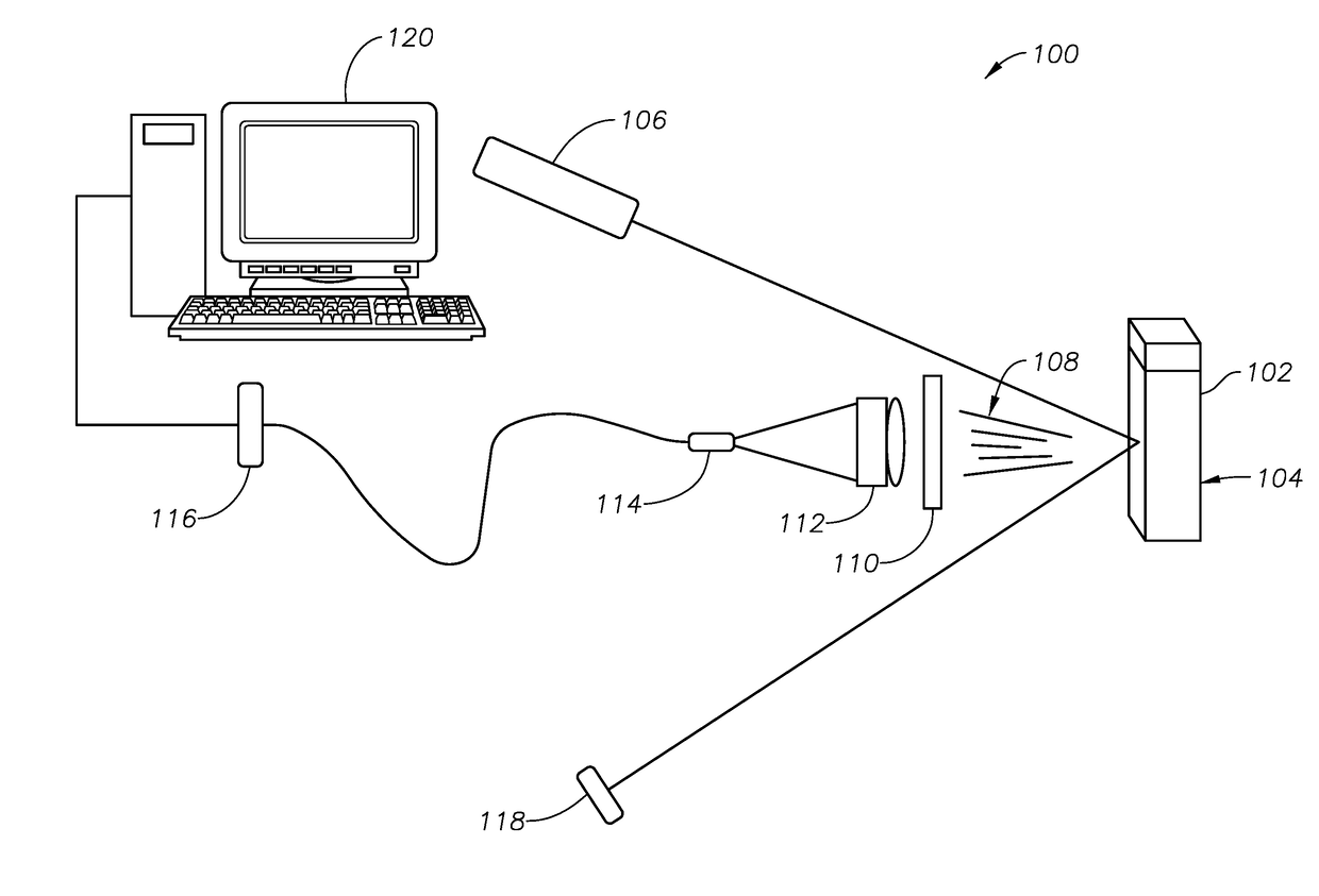
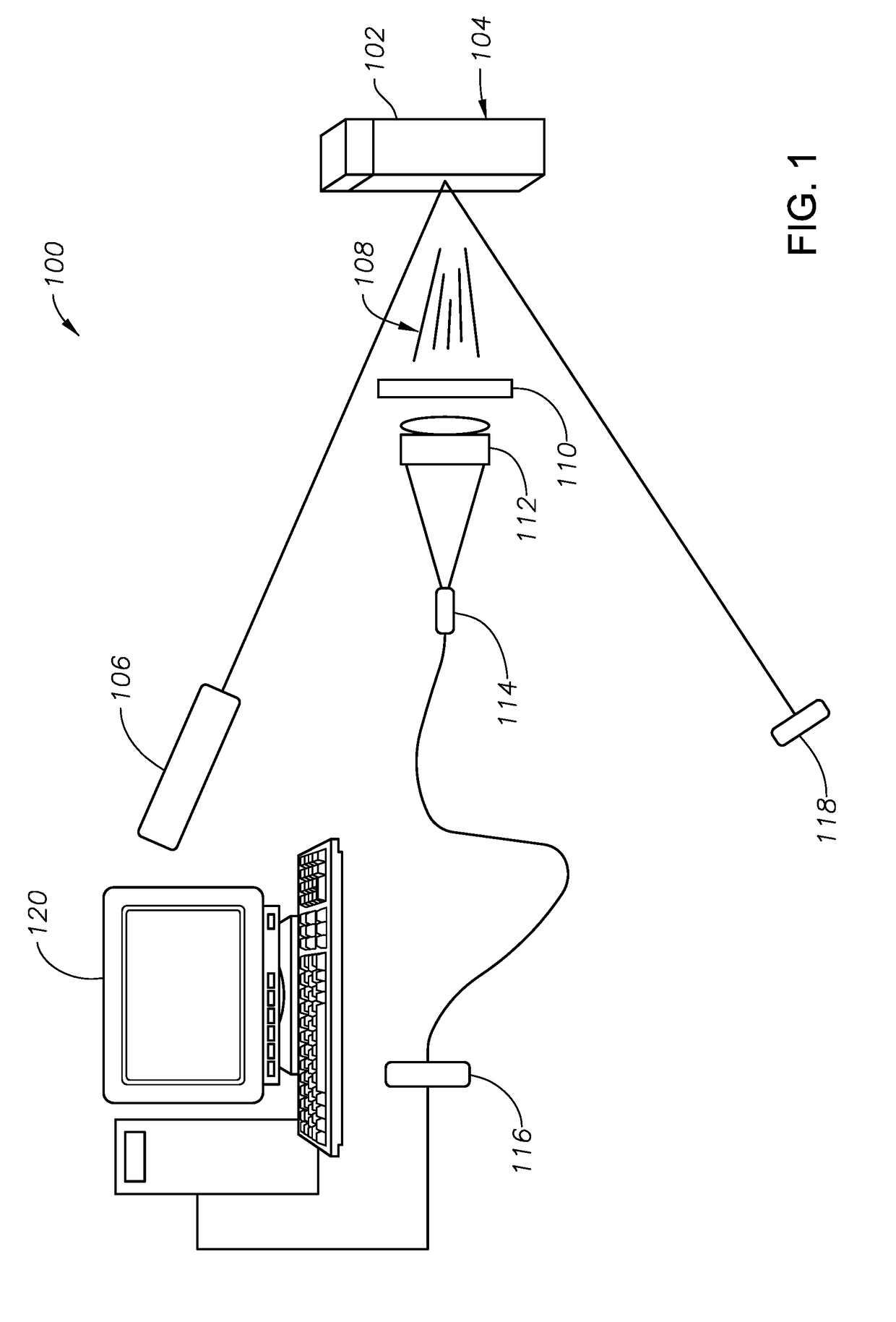
[0022]Embodiments of the disclosure include systems, devices, computer-readable media, and methods for determining the viscosity of a lubrication oil from the induced fluorescence rise-time of the oil. As described infra, the rate of change of the induced fluorescence intensity, as represented by the fluorescence rise-time, directly correlates with the viscosity of the lubrication oil. As used in the disclosure, a lubrication oil may include, for example, an engine oil, a motor oil, a gear oil, a tur...


PUM


Abstract

Methods, media, and devices for determining the deterioration of an oil by determining the viscosity of the oil from fluorescence rise-time are provided. A sample of an oil from a machine may be obtained. The oil sample may be irradiated using a light source such a laser to induce fluorescence in the oil sample. The induced fluorescence may be filtered and collimated before being detecting by a photodiode. The relative intensity of the fluorescence may be measured over a time period at a sample rate and used to determine the fluorescence rise-time of the oil sample. The viscosity of the oil sample may be determined from the fluorescence rise-time. The determined viscosity may be compared to viscosity threshold value to determine the deterioration of the oil.

Description


Claims


Application Information

Patent Timeline
Owner SAUDI ARABIAN OIL CO
Why Eureka
Try Eureka