Method and apparatus for magnetic resonance imaging

Active Publication Date: 2017-07-20
SIEMENS HEALTHCARE GMBH
View PDF0 Cites 3 Cited by
  • Summary
  • Abstract
  • Description
  • Claims
  • Application Information

AI Technical Summary

Benefits of technology

[0050]For the phase correction, correction phase values calculated on the basis of the at least two recorded navigator slices are used. The phase correction can include, for example, a correction or compensation of a background phase in the first set of magnetic resonance scan data and the second set of magnetic resonance scan data. A compensation of the background phase of this kind can be beneficial with the use of a functional magnetic-resonance technique and/or with the use of an echo-planar imaging technique. The phase correction can also include a correction of phase influences of a motion of the object to be examined, for example a respiratory motion.

Problems solved by technology

The physiological parameters of the object to be examined can result in an unwanted change in the magnetic resonance scan data acquired during the magnetic resonance imaging, for example they c

Method used


Image

  • Method and apparatus for magnetic resonance imaging
  • Method and apparatus for magnetic resonance imaging
  • Method and apparatus for magnetic resonance imaging

Examples


second embodiment

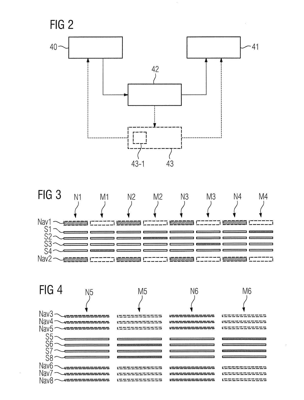
[0078]FIG. 3 is a schematic illustration of the image scans and navigator scan according to a method according to the invention.

[0079]FIG. 3 shows an exemplary alternating sequence of navigator scans N1, N2, N3, N4 and image scans M1, M2, M3, M4. For each of the scans, in each case the at least one slice, which is excited and read out in the respective scan is shown. This at least one slice is then depicted for the respective scan as a filled-in rectangle, while the other slices are depicted as not filled-in.

[0080]The examination region shown in FIG. 3, from which the magnetic resonance scan data is acquired, includes by way of example four scan data slices S1, S2, S3, S4. Two navigator slices Nav1, Nav2 are arranged on opposite sides of the examination region. In this context, the first navigator slice Nav1 is arranged above the examination region, wherein the second navigator slice Nav2 is arranged below the examination region.

[0081]In the case shown in FIG. 3, the navigator slice...

third embodiment

[0085]FIG. 4 is a schematic illustration of the image scans and navigator scan according to a method according to the invention.

[0086]FIG. 4 shows the example, two navigator scans N5, N6, which alternate with two image scans M5, M6. As in FIG. 3, once again the slices that are excited or read out are depicted as filled-in and the slices that are not excited or read out slices are depicted as not filled-in.

[0087]Once again, the examination region should include four scan data slices S5, S6, S7, S8. However, unlike the example in FIG. 3, in each diagnostic imaging scan M5, M6 in each case two scan data slices S5, S6, S7, S8 are excited and read out with a multiband factor of two.

[0088]Each navigator scan N5, N6 has an example, a recording of six navigator slices Nav3, Nav4, Nav5, Nav6, Nav7, Nav8, wherein three first navigator slices Nav3, Nav4, Nav5 are arranged on a first side of the opposite sides of the examination region and three second navigator slices Nav6, Nav7, Nav8 are arra...

fourth embodiment

[0090]FIG. 5 is a schematic illustration of a phase correction according to the method according to the invention.

[0091]FIG. 5 depicts a possibility for illustrating a slice-specific extraction of phase correction parameters for individual scan data slices 56, 57, 58 from two navigator slices 54, 55. In this context, for the example in FIG. 5, the scan data slices 56, 57, 58 and the navigator slices 54, 55 should be positioned in a head of the object to be examined 15. In this context, the arrangement of slices is shown in the image window at the upper right image edge in FIG. 5.

[0092]For the example in FIG. 5, the scan data slices 56, 57, 58 are acquired by means of an acquisition scheme at three different time points 59, 60, 61. The navigator slices 54, 55 are excited and read out simultaneously by a multiband-radio-frequency pulse with a multiband factor of 2.

[0093]It is now possible to determine a time-dependent first phase value from the first navigator slice 54, while a time-d...


PUM


Abstract

In a method and apparatus for magnetic resonance imaging, a first diagnostic imaging scan is executed that includes a recording of first set of magnetic resonance scan data from a first subregion of an examination region, and a second diagnostic imaging scan is executed that includes a recording of a second set of magnetic resonance scan data from a second subregion of the examination region. A navigator scan is executed chronologically between the first diagnostic imaging scan and second diagnostic imaging scan, wherein the navigator scan includes a recording of at least two navigator slices arranged on opposite sides of the examination region.

Description

BACKGROUND OF THE INVENTION[0001]Field of the Invention[0002]The invention relates to a method for magnetic resonance imaging, and a magnetic resonance apparatus and a non-transitory data storage medium for implementing such a method[0003]Description of the Prior Art[0004]In a magnetic resonance device, also called a magnetic resonance tomography system, the body to be examined of an object to be examined, for example a patient, a healthy training volunteer or a phantom, is exposed to a relatively high basic magnetic field with the use of a basic field magnet, for example 1.5 or 3 or 7 tesla. In addition, gradient pulses are activated with the use of a gradient coil arrangement. A radio-frequency antenna arrangement emits radio-frequency pulses, for example excitation pulses, from suitable antennas that cause the nuclear spins of specific atoms excited to resonance by these radio-frequency pulses to be tilted by a defined flip angle relative to the magnetic field lines of the basic ...

Claims


Application Information

Patent Timeline
IPC IPC(8): G01R33/567
CPCG01R33/567G01R33/5676G01R33/4835G01R33/5616G01R33/56509
Inventor ZELLER, MARIO
Owner SIEMENS HEALTHCARE GMBH
Why Eureka
Try Eureka