
Decoding method, memory storage device and memory control circuit unit

a memory storage device and control circuit technology, applied in the direction of coding, error correction/detection using convolutional codes, instruments, etc., can solve the problems of reducing the reliability of the memory cells, reducing the efficiency of subsequent decoding, and reducing the error rate of data stored in the memory cells. , to achieve the effect of improving the decoding efficiency

Active Publication Date: 2017-07-20
SHENZHEN EPOSTAR ELECTRONICS LTD
View PDF0 Cites 19 Cited by
  • Summary
  • Abstract
  • Description
  • Claims
  • Application Information

AI Technical Summary

Benefits of technology

The present patent is about a method for improving decoding efficiency in memory storage devices. It involves updating channel reliability information for different usage levels of memory cells in real-time. This is done by analyzing data stored in a physical unit and obtaining the distribution of threshold voltage for various bit values. By using this information, data stored in that physical unit can be decoded more efficiently. Overall, this method helps to improve the performance of memory storage devices.

Problems solved by technology

Along with increase of a usage level of the rewritable non-volatile memory module, reliability of the memory cells is decreased, which may cause errors of data stored in the memory cells.
However, in some decoding procedures performed based on concept of probability, if some parameters used in the corresponding decoding procedures are not adaptively adjusted along with different usage levels of the memory cells, it may cause reduction of subsequent decoding efficiency.
Furthermore, citation or identification of any document in this application is not an admission that such document is available as prior art to the present disclosure, or that any reference forms a part of the common general knowledge in the art.

Method used


Image

  • Decoding method, memory storage device and memory control circuit unit
  • Decoding method, memory storage device and memory control circuit unit
  • Decoding method, memory storage device and memory control circuit unit

Examples


Embodiment Construction

[0028]Reference will now be made in detail to the present preferred embodiments of the disclosure, examples of which are illustrated in the accompanying drawings. Wherever possible, the same reference numbers are used in the drawings and the description to refer to the same or like parts.

[0029]Generally, a memory storage device (which is also referred to as a memory storage system) includes a rewritable non-volatile memory module and a controller (which is also referred to as a control circuit). The memory storage device is generally used together with a host system, and the host system can write data into the memory storage device and read data from the memory storage device.

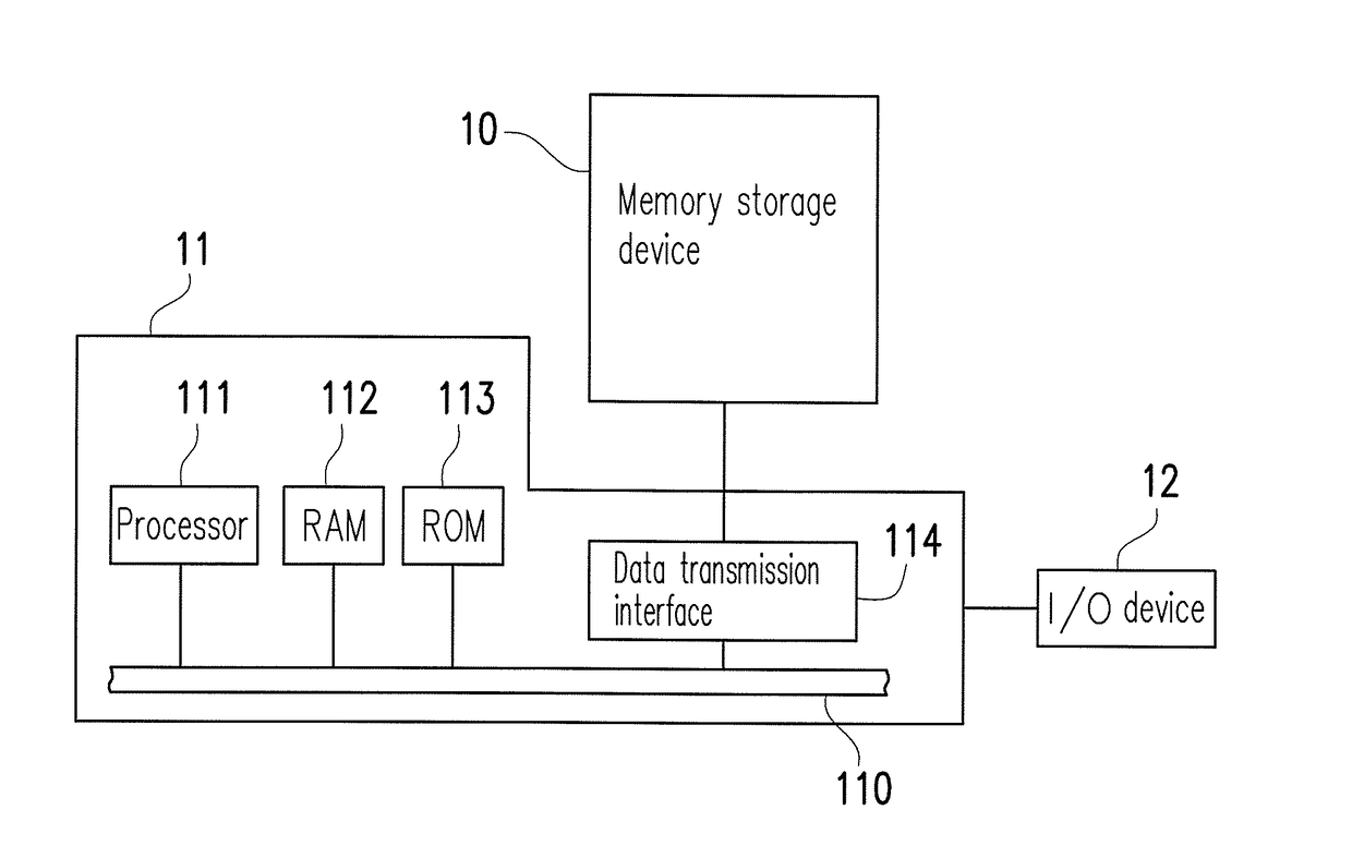
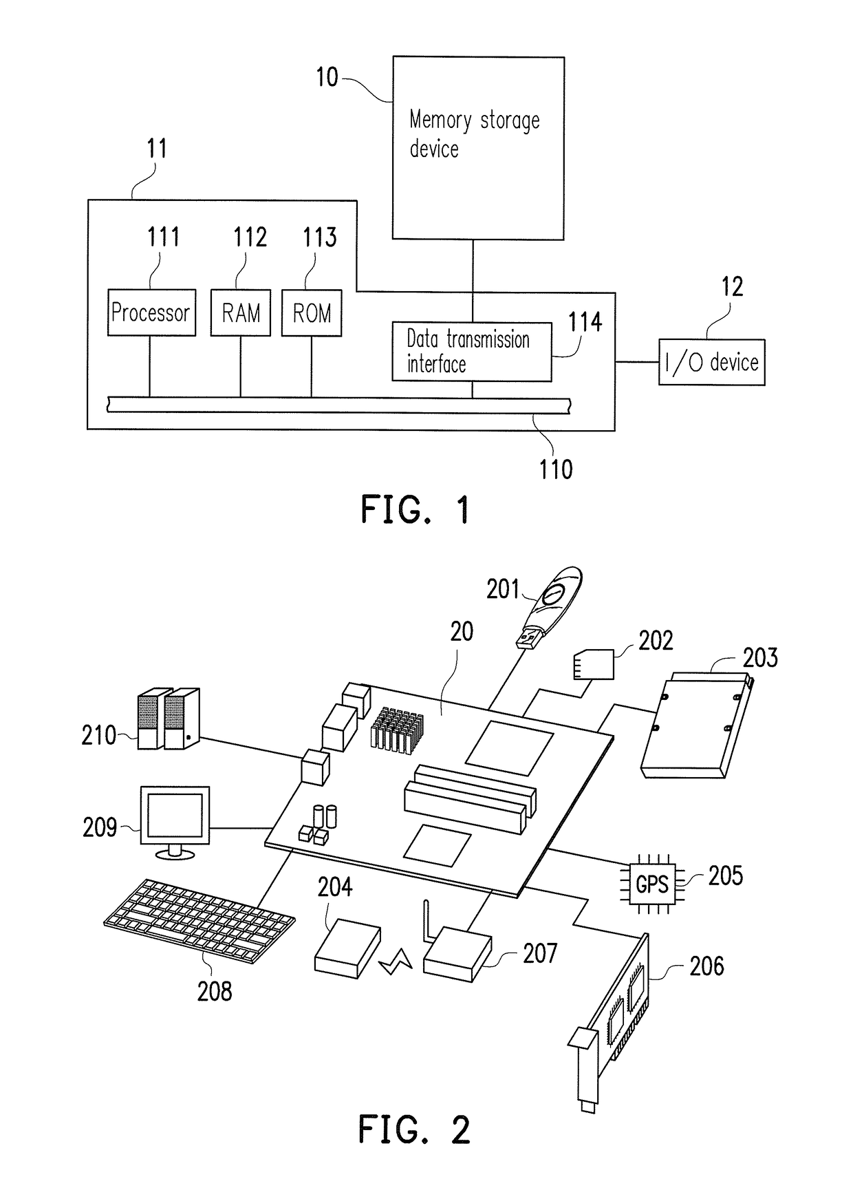
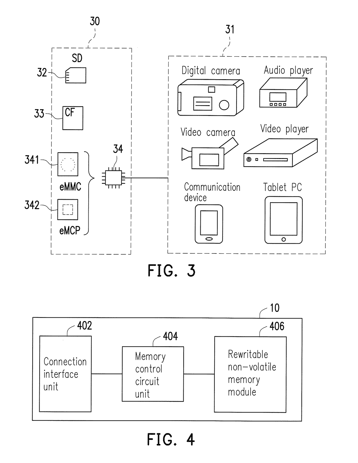
[0030]FIG. 1 is a schematic diagram of a host system, a memory storage device and an input / output (I / O) device according to an exemplary embodiment of the present disclosure. FIG. 2 is a schematic diagram of a host system, a memory storage device and an I / O device according to another exemplary embodiment of th...


PUM


Abstract

A decoding method, a memory storage device and a memory control circuit unit are provided. The method includes: programming first data into a first physical unit of a rewritable non-volatile memory module; reading the first physical unit to obtain second data; obtaining a first threshold voltage distribution of a first bit-value and a second threshold voltage distribution of a second bit-value according to the first data and the second data, wherein the first bit-value and the second bit-value are different; calculating first channel reliability information corresponding to the first physical unit according to the first threshold voltage distribution and the second threshold voltage distribution; and decoding third data stored in the first physical unit according to the first channel reliability information. Therefore, decoding efficiency for the first physical unit is improved.

Description

CROSS-REFERENCE TO RELATED APPLICATION[0001]This application claims the priority benefit of Taiwan application serial no. 105101654, filed on Jan. 20, 2016. The entirety of the above-mentioned patent application is hereby incorporated by reference herein and made a part of this specification.BACKGROUND[0002]Technology Field[0003]The present disclosure relates to a decoding technique, in particular, relates to a decoding method, a memory storage device and a memory control circuit unit.[0004]Description of Related Art[0005]Digital cameras, mobile phones and MP3 players are quickly developed in recent years, so that consumer demands for storage media have also rapidly increased. Since a rewritable non-volatile memory module (for example, a flash memory) has characteristics of data non-volatility, low power consumption, small volume, and non-mechanical structure, etc., it is adapted to be built in the aforementioned various portable multimedia devices.[0006]Generally, the smallest unit...

Claims


Application Information

Patent Timeline
Patent Type & Authority Applications(United States)
IPC IPC(8): G06F11/10G11C16/10G11C16/26G11C29/52
CPCG06F11/1068G11C29/52H03M13/3715G11C16/26G11C16/10G11C29/021G11C29/028H03M13/1111H03M13/152H03M13/23H03M13/2957H03M13/6325G06F11/1048
Inventor HSIAO, YU-HUAYEN, HENG-LIN
Owner SHENZHEN EPOSTAR ELECTRONICS LTD
Learn More