Abrasion resistant textile sleeve, improved multifilament yarn therefor and methods of construction thereof

a textile sleeve and multi-filament technology, applied in the field of textile sleeves, can solve the problems of increasing cost, bulk, stiffness and weight of the sleeve, and reducing so as to reduce the cost, weight and the outer envelope of the sleeve, and improve the abrasion resistance of the sleev

Pending Publication Date: 2017-07-20
FEDERAL MOGUL POWERTAIN LLC
View PDF4 Cites 14 Cited by
  • Summary
  • Abstract
  • Description
  • Claims
  • Application Information

AI Technical Summary

Benefits of technology

[0006]One aspect of the invention provides an abrasion resistant, flexible textile sleeve for routing and protecting an elongate member contained therein from exposure to abrasion. The sleeve has a wall extending lengthwise along a longitudinal axis between opposite ends, wherein the wall is configured to bound a cavity, in which the elongate member is contained and protected. The wall is constructed, at least in part, from improved multifilament yarn, which enhances the abrasion resistance of the sleeve wall, while also allowing the fabric density of the wall to remain relatively low, given the degree of abrasion resistance provided, thereby reducing cost, weight and the outer envelope of the sleeve, while also enhancing the flexibility of the sleeve. The improved multifilament yarn includes a plurality of fibers and / or filaments, referred to hereafter for convenience as filaments (being distinguishable by length, with filaments being much longer than fibers, and can extend the entire length of the yarn as continuous, unbroken members, in contrast to much shorter fibers), with at least some of the filaments being provided as “low-melt” filaments and with at least some of the filaments being provided as “standard,”“non-low-melt” filaments. By “low-melt” it will be recognized by one skilled in the art that the low-melt fibers melt, at least in part, at a lower temperature as compared to the standard melt temperature fibers, if the standard filaments are capable of melting at all. As such, during production of the sleeve, upon forming the textile, interlaced wall of the sleeve, the wall is subjected to a predetermined heat treatment process, whereupon the low-melt filaments are caused to melt, at least in part, while the standard melt temperature filaments remain entirely or substantially unmelted. The at least partially melted low-melt filaments act as glue to bond all the filaments, including the standard, non-low-melt temperature filaments, of the multifilament yarn to one another. Accordingly, the individual filaments are prevented or inhibited from moving in sliding relation relative to one another, which in turn reduces the abrasion between the individual filaments of the multifilament yarn, thus improving the resistance of the sleeve wall to wear from abrasion. However, although the melted filaments are bonded to one another, the filaments, and wall formed thereby, remain highly flexible, thereby allowing the resulting sleeve to be routed about meandering paths and corners. As such, with the sleeve wall remaining substantially un-abraded in use, the elongate members contained therein are optimally protected against external sources of abrasion and contamination.

Problems solved by technology

Unfortunately, although known sleeves can be effective at providing such protection to elongate members against abrasion and contamination, they typically have a relative high fabric density, due to the need for increased amounts of yarn material to provide the desired protection against both abrasion and contamination, thereby adding cost, bulk, stiffness and weight to the sleeve.

Method used


Image

  • Abrasion resistant textile sleeve, improved multifilament yarn therefor and methods of construction thereof
  • Abrasion resistant textile sleeve, improved multifilament yarn therefor and methods of construction thereof
  • Abrasion resistant textile sleeve, improved multifilament yarn therefor and methods of construction thereof

Examples


Embodiment Construction

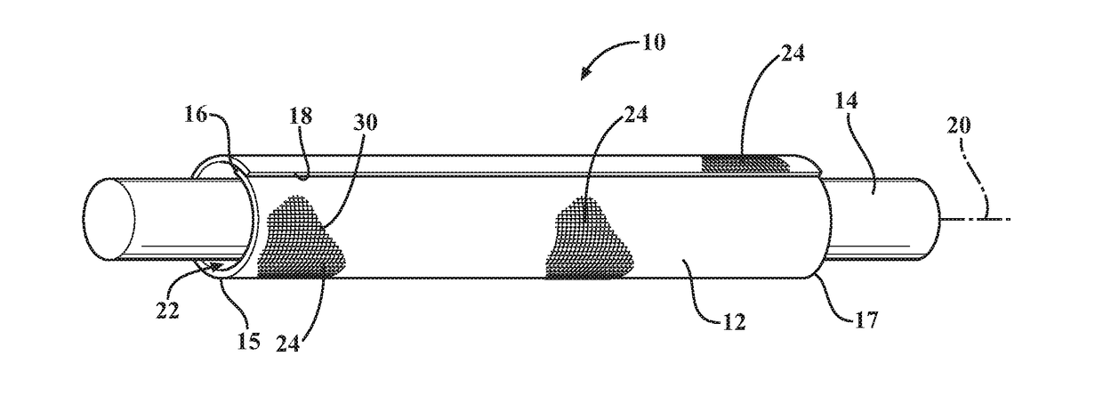
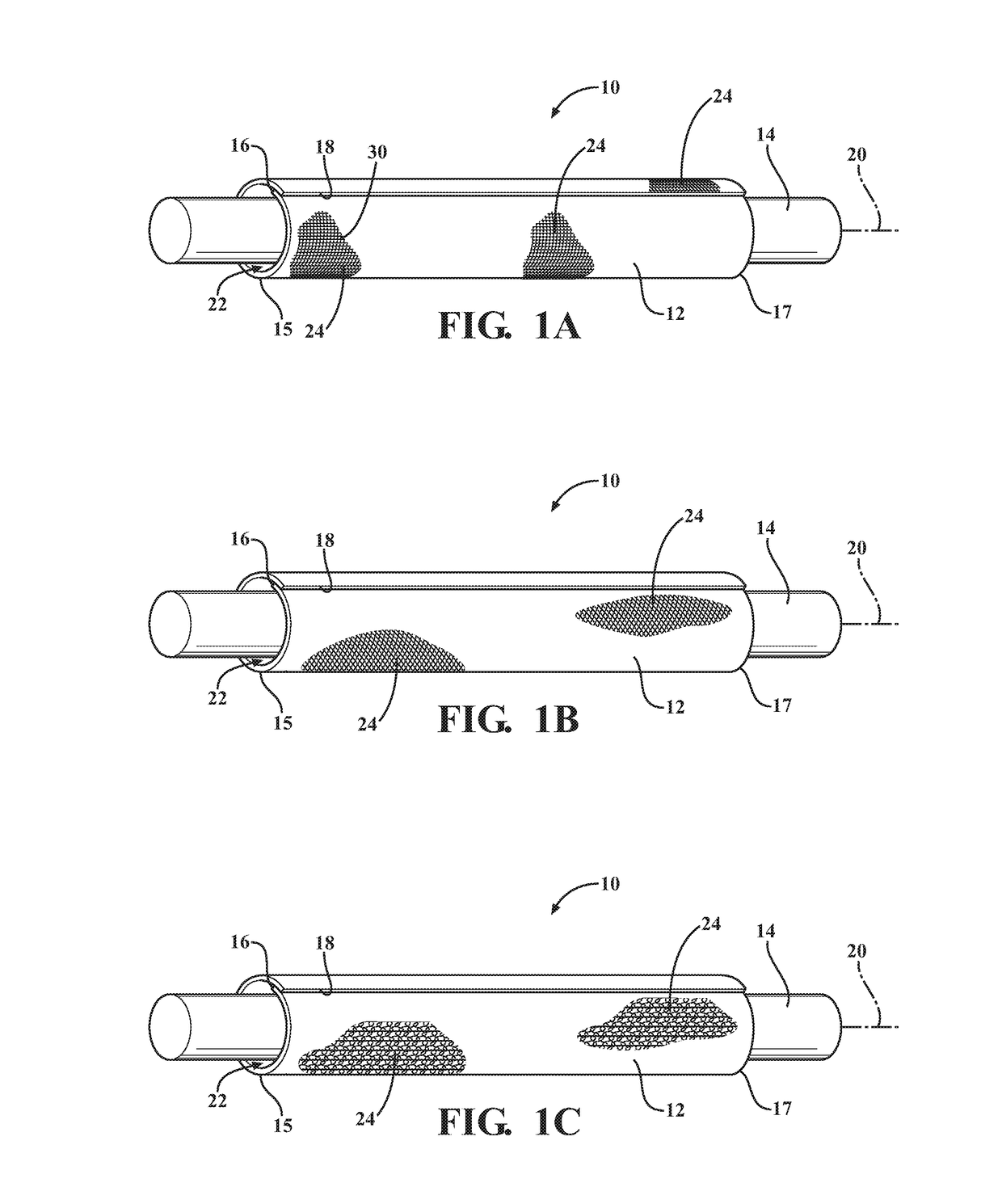
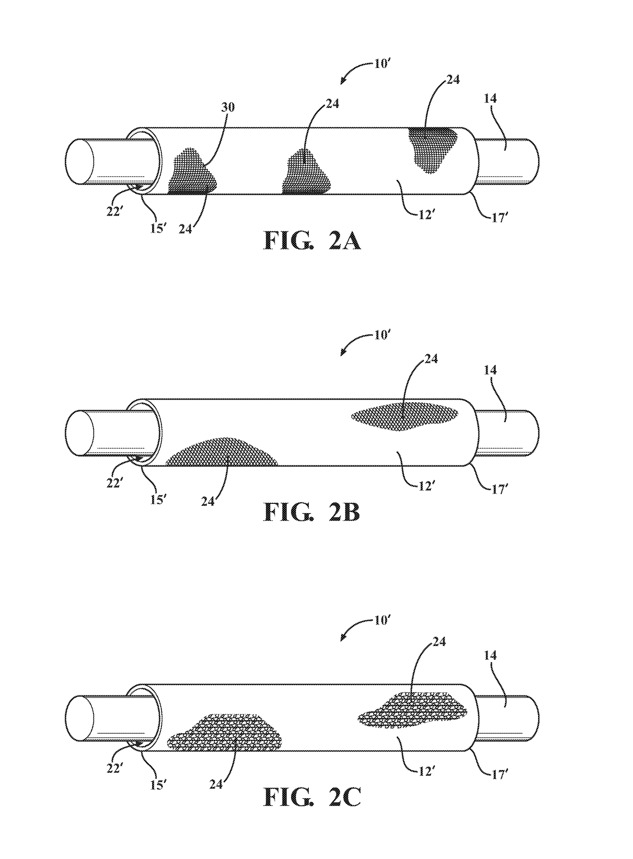
[0041]Referring in more detail to the drawings, FIGS. 1A-1C show schematic representations of textile sleeves, referred to hereafter as sleeve 10, constructed in accordance with various aspects of the invention. The sleeve 10 is shown having a wrappable elongate wall 12 for routing and protecting an elongate member 14, such as wires, a wire harness, or tube, for example, from exposure to abrasion and the ingress of contamination, debris and the like. The elongate wall 12 has opposite edges 16, 18 extending lengthwise along a longitudinal, central axis 20 between opposite ends 15, 17, wherein the edges 16, 18 are configured to be wrapped into overlapping relation with one another in “cigarette wrapped” fashion to fully enclose the elongate member 14 within a central cavity 22 of the sleeve 10. The cavity 22 is readily accessible along the full length of the central axis 20 so that the elongate member 14 can be readily disposed radially into the cavity 22, and conversely, removed from...


PUM

PropertyMeasurementUnit
melt temperatureaaaaaaaaaa
temperatureaaaaaaaaaa
diameteraaaaaaaaaa

Abstract

A textile sleeve for routing and protecting an elongate member against abrasion and method of construction thereof are provided. The sleeve includes a flexible wall having a plurality of yarns interlaced with one another. At least some of the plurality of yarns are provided as improved multifilament yarns having low-melt filaments and non-low-melt filaments. The low-melt filaments have a first melt temperature and the non-low-melt filaments having a second melt temperature, with the second melt temperature being greater than the first melt temperature. The low-melt filaments are bonded with the non-low-melt filaments to prevent relative sliding movement therebetween.

Description

CROSS-REFERENCE TO RELATED APPLICATION[0001]This application claims the benefit of U.S. Provisional Application Ser. No. 62 / 280,923, filed Jan. 20, 2016, which is incorporated herein by reference in its entirety.BACKGROUND OF THE INVENTION[0002]1. Technical Field[0003]This invention relates generally to textile sleeves for protecting elongate members, and more particularly to abrasion resistant, flexible textile sleeves and to methods of construction thereof.[0004]2. Related Art[0005]It is known to wrap elongate members in protective sleeves to provide protection to elongate members contained therein against abrasion and contamination. Unfortunately, although known sleeves can be effective at providing such protection to elongate members against abrasion and contamination, they typically have a relative high fabric density, due to the need for increased amounts of yarn material to provide the desired protection against both abrasion and contamination, thereby adding cost, bulk, stif...

Claims


Application Information

Patent Timeline
Patent Type & Authority Applications(United States)
IPC IPC(8): H01B7/18H01B17/58D06N7/00D03D15/567
CPCH01B7/18D06N2209/105H01B17/58D06N7/00D03D1/0041H02G3/0481H02G3/04D04C1/02D04C1/12D10B2401/041D03D15/567D03D15/587D03D1/0043D10B2505/12G02B6/4432
Inventor KHOSROSHAHI, ALIGAO, TIANQIKRAUSER, LEIGHLI, YIMEHBUBANI, RITESH
Owner FEDERAL MOGUL POWERTAIN LLC
Why Eureka
Try Eureka