Supercharge Your Innovation With Domain-Expert AI Agents!

Turbine Engine Cleaning Systems and Methods

a gas turbine engine and cleaning system technology, applied in the field of turbine engines, can solve the problems of increasing the roughness of turbine components, affecting the performance of turbine components of aircraft engines used to propel aircraft through certain routes, and affecting the performance of turbine components

Active Publication Date: 2017-07-27
GENERAL ELECTRIC CO
View PDF3 Cites 5 Cited by
  • Summary
  • Abstract
  • Description
  • Claims
  • Application Information

AI Technical Summary

Benefits of technology

The technical effects of this patent are not clearly stated, but it can be inferred that it relates to a new invention or innovation that solves a specific problem or issue. The text references the "technical advantages" of the invention, which may include its benefits or improvements. This information can be useful for scientists, engineers, and other researchers who are working on the invention.

Problems solved by technology

Aircraft engines used to propel aircraft through certain routes often experience significant fouling due to heavy environmental particulate matter intake during flight, idling, take-off, and landing.
Environmental fouling degrades performance in turbine components of such aircraft engines.
For example, one known mechanism for fouling is the increased roughness of turbine components caused by mineral dust ingestion.
Specifically, this increased roughness can result from the formation of micropits caused by particle impact.
Subsequently, mineral dust particles accumulate in these pits and block cooling passages by forming layers of fouling material therein.
Consequently, water wash treatments, which are frequently used to clean the turbine components, often are not successful in removing the accumulated mineral dust and its secondary reaction products.
This problem can become magnified in the internal portions of a turbine component.
Although the internal portions of the components may be susceptible to fouling, they can be virtually impossible to reach while assembled or installed on-wing.
Water wash treatments performed on wing are often unable to reach these portions at all.
The result is often time-consuming and expensive.

Method used


Image

  • Turbine Engine Cleaning Systems and Methods
  • Turbine Engine Cleaning Systems and Methods
  • Turbine Engine Cleaning Systems and Methods

Examples


Embodiment Construction

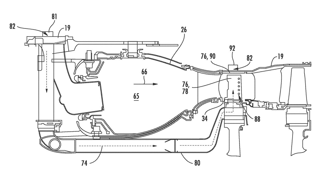
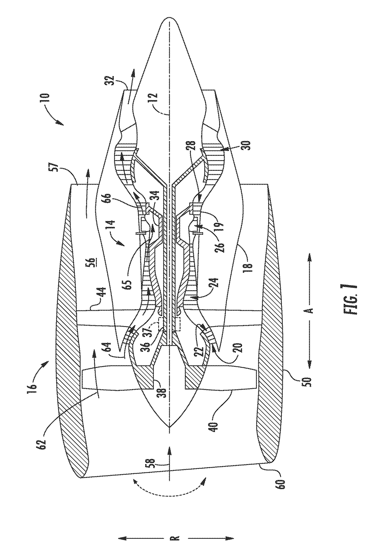
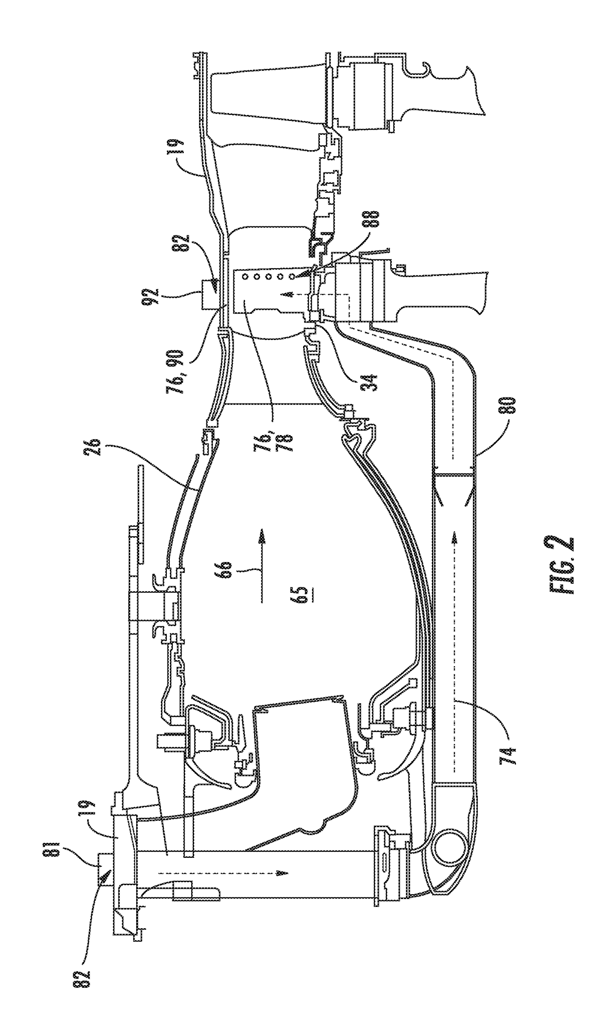
[0020]Reference now will be made in detail to embodiments of the invention, one or more examples of which are illustrated in the drawings. Each example is provided by way of explanation of the invention, not limitation of the invention. In fact, it will be apparent to those skilled in the art that various modifications and variations can be made in the present invention without departing from the scope or spirit of the invention. For instance, features illustrated or described as part of one embodiment can be used with another embodiment to yield a still further embodiment. Thus, it is intended that the present invention covers such modifications and variations as come within the scope of the appended claims and their equivalents.

[0021]As used herein, the terms “first,”“second,” and “third” may be used interchangeably to distinguish one component from another and are not intended to signify location or importance of the individual components.

[0022]The terms “upstream” and “downstrea...


PUM


Abstract

A system and method of cleaning a turbine engine are provided. The method may include inserting, directing and evacuating a cleaning agent. Inserting may include inserting the cleaning agent through a predefined access port into a cooling cavity defined by an internal wall of an assembled turbine component, while directing may include directing the cleaning agent against the internal wall to remove a foreign material therefrom. Evacuating may include evacuating the cleaning agent from the cooling cavity.

Description

FIELD OF THE INVENTION[0001]The present subject matter relates generally to turbine engines, and more particularly, to cleaning systems and methods for a gas turbine engine.BACKGROUND OF THE INVENTION[0002]Aircraft engines used to propel aircraft through certain routes often experience significant fouling due to heavy environmental particulate matter intake during flight, idling, take-off, and landing. Environmental fouling degrades performance in turbine components of such aircraft engines. For example, one known mechanism for fouling is the increased roughness of turbine components caused by mineral dust ingestion. Specifically, this increased roughness can result from the formation of micropits caused by particle impact. Subsequently, mineral dust particles accumulate in these pits and block cooling passages by forming layers of fouling material therein. High temperatures on surfaces in downstream stages of the turbine result in thermal alteration and solid-state mineral reaction...

Claims


Application Information

Patent Timeline
Patent Type & Authority Applications(United States)
IPC IPC(8): B08B9/032B08B9/04B08B3/08F02C3/04B08B7/00
CPCB08B9/0326F02C3/04F05D2230/72B08B3/08B08B9/04B08B7/00F01D25/002F05D2220/323B08B7/02B24C3/327F01D5/081F01D5/186F05D2270/11F05D2220/32B08B9/00Y02T50/60
Inventor ERIKSEN, MICHAEL EDWARDBOS, MATTHEWTIBBETTS, NICOLE JESSICASCHEPER, MICHAELZELTWANGER, ERIC
Owner GENERAL ELECTRIC CO
Features
  • R&D
  • Intellectual Property
  • Life Sciences
  • Materials
  • Tech Scout
  • Unparalleled Data Quality
  • Higher Quality Content
  • 60% Fewer Hallucinations
Learn More