Internal combustion engine

Active Publication Date: 2017-07-27
TOYOTA JIDOSHA KK
View PDF6 Cites 9 Cited by
  • Summary
  • Abstract
  • Description
  • Claims
  • Application Information

AI Technical Summary

Benefits of technology

[0007]It is possible to reduce the combustion noise during autoignition combustion by causing the injected fuel of

Problems solved by technology

In a conventional spark ignition combustion internal combustion engine which uses a spark plug to ignite part of the air-fuel mixture and uses propagation of the ignited flame to burn the remaining air-fu

Method used


Image

  • Internal combustion engine
  • Internal combustion engine
  • Internal combustion engine

Examples


Embodiment Construction

s of the Invention

[0007]It is possible to reduce the combustion noise during autoignition combustion by causing the injected fuel of the secondary fuel injection to be autoignited after the injected fuel of the primary fuel injection is autoignited.

BRIEF DESCRIPTION OF DRAWINGS

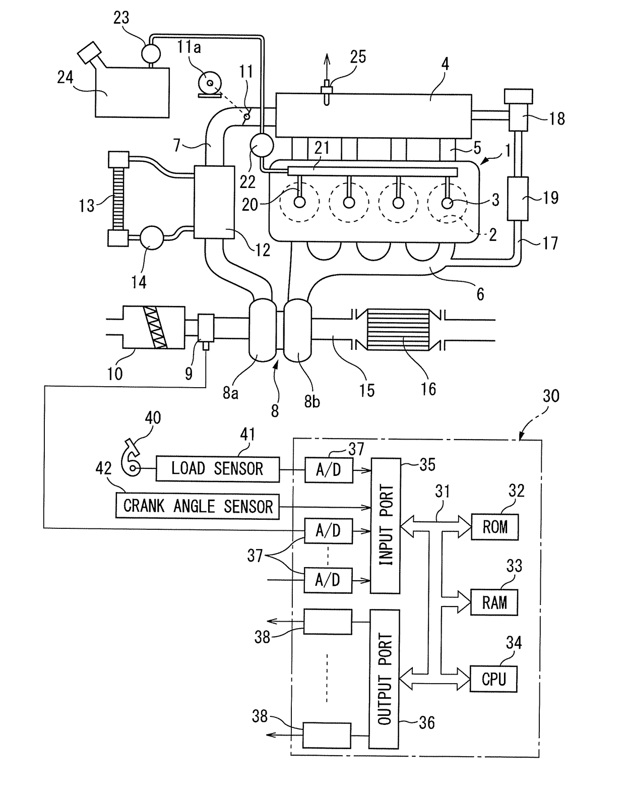
[0008]FIG. 1 is an overall view of an internal combustion engine using gasoline as a fuel.

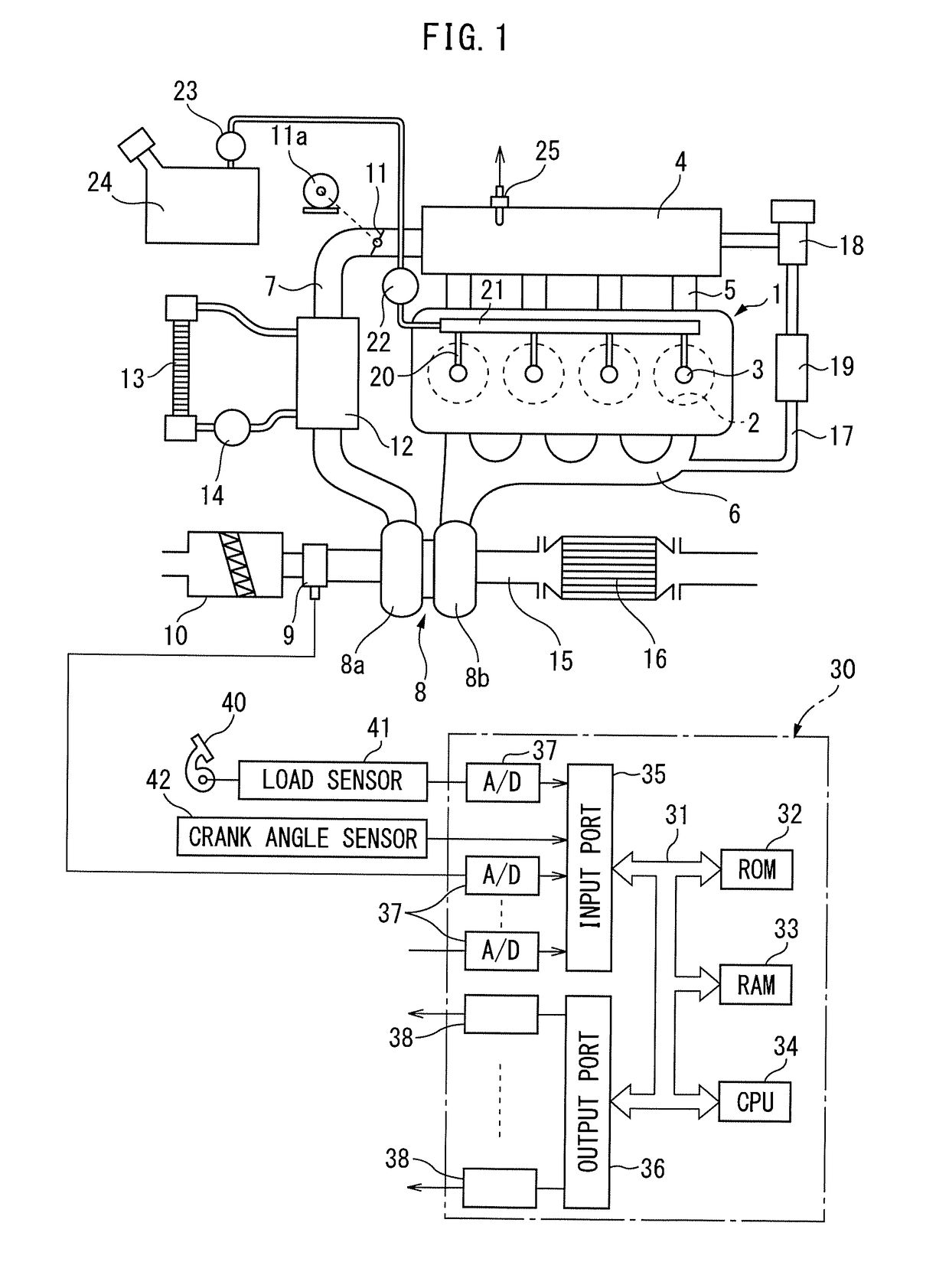
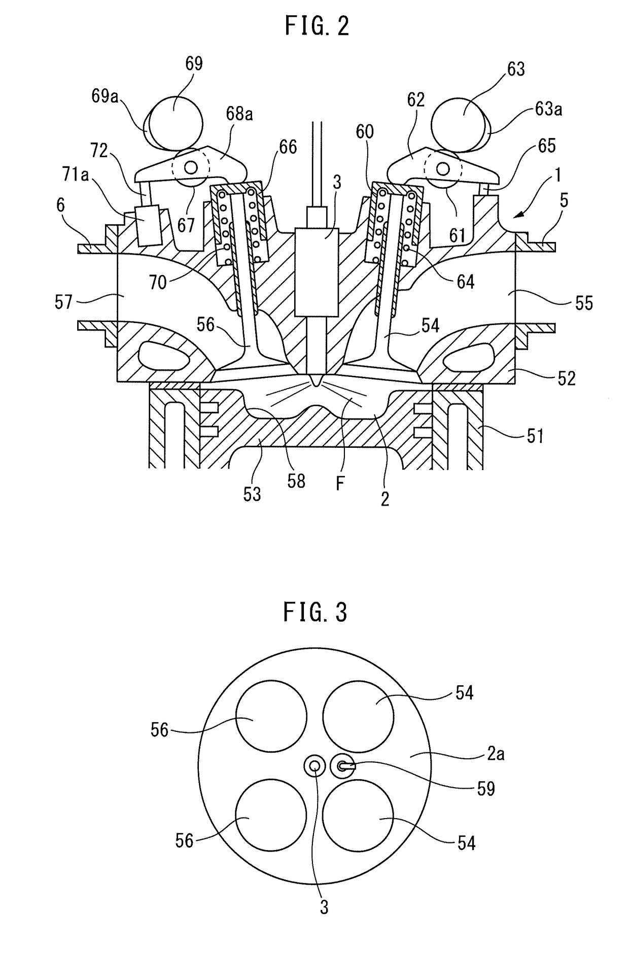
[0009]FIG. 2 is a cross-sectional view of an engine body.

[0010]FIG. 3 is a bottom view of a top wall surface of a combustion chamber shown in FIG. 2.

[0011]FIG. 4 is a plan view of an end part of a cylinder head in a longitudinal direction.

[0012]FIG. 5A and FIG. 5B are views showing a cross-section A-A and a cross-section B-B in FIG. 4, respectively.

[0013]FIG. 6 is a cross-sectional view of a variable valve timing mechanism for an exhaust valve.

[0014]FIG. 7A and FIG. 7B are views showing changes in an exhaust valve lift and an intake valve lift.

[0015]FIG. 8 is a view showing an autoignition region RR.

[0016]FIG. 9A and FIG....


PUM


Abstract

An internal combustion engine comprising the fuel injector arranged in the combustion chamber. The primary fuel injection and the secondary fuel injection from the fuel injector are successively performed to cause autoignition of an injected fuel of the primary fuel injection and autoignition of an injected fuel of the secondary fuel injection. A temperature region suppressing change of an ignition delay time where a change of ignition delay time with respect to a rise in temperature in the combustion chamber is suppressed appears in the compression stroke at a temperature in the combustion chamber of 700K to 900K. The secondary fuel injection is performed if the temperature in the combustion chamber is a temperature within the temperature region suppressing change of the ignition delay time during the compression stroke. The primary fuel injection is performed during the compression stroke or suction stroke before the temperature in the combustion chamber reaches a temperature in the temperature region suppressing change of the ignition delay time at a fuel injection timing at which the injected fuel of the secondary fuel injection is autoignited after the injected fuel of the primary fuel injection is autoignited.

Description

CROSS-REFERENCE TO RELATED APPLICATION[0001]The present application claims priority to Japanese Patent Application No. 2016-011443 filed on Jan. 25, 2016, which is incorporated herein by reference in its entirety.TECHNICAL FIELD[0002]Embodiments of the present invention relate to an internal combustion engine.BACKGROUND ART[0003]In an internal combustion engine, the higher the compression ratio, the more the thermal efficiency is improved, while the thinner the air-fuel ratio of the air-fuel mixture, the more the fuel consumption is improved. In a conventional spark ignition combustion internal combustion engine which uses a spark plug to ignite part of the air-fuel mixture and uses propagation of the ignited flame to burn the remaining air-fuel mixture, the compression ratio cannot be raised because knocking would occur. Further, the air-fuel ratio of the air-fuel mixture cannot be made thinner because the ignited flame can no longer propagate. As opposed to this, autoignition comb...

Claims


Application Information

Patent Timeline
IPC IPC(8): F02D41/30F02D13/02
CPCF02D41/3023F02D2200/1002F02D2200/021F02D13/0215F02D35/02F02D37/02F02D41/0002F02D41/402F01L1/3442F02D13/0276F02D2041/001F02D2200/025F02D41/2409F02D41/3035F02D41/3041F02D41/401F02B23/101F02B29/0493F02D35/025F02D2200/0414F02M26/05F02D13/0219F02D13/0246F02D13/0257F02D13/0273Y02T10/12Y02T10/40
Inventor OCHI, YUTA
Owner TOYOTA JIDOSHA KK
Why Eureka
Try Eureka