
Method and apparatus for a hardness test block

a test block and hardness technology, applied in the field of hardness testing equipment and methods, can solve the problems of limiting the layout method of test sites to 65 test sites per block, affecting the hardness of the material, and affecting the quality of the test block

Inactive Publication Date: 2017-07-27
MAZZOLENI GIANCARLO +1
View PDF1 Cites 2 Cited by
  • Summary
  • Abstract
  • Description
  • Claims
  • Application Information

AI Technical Summary

Benefits of technology

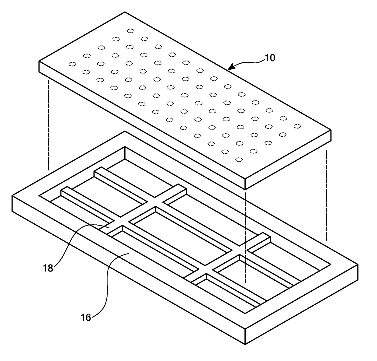
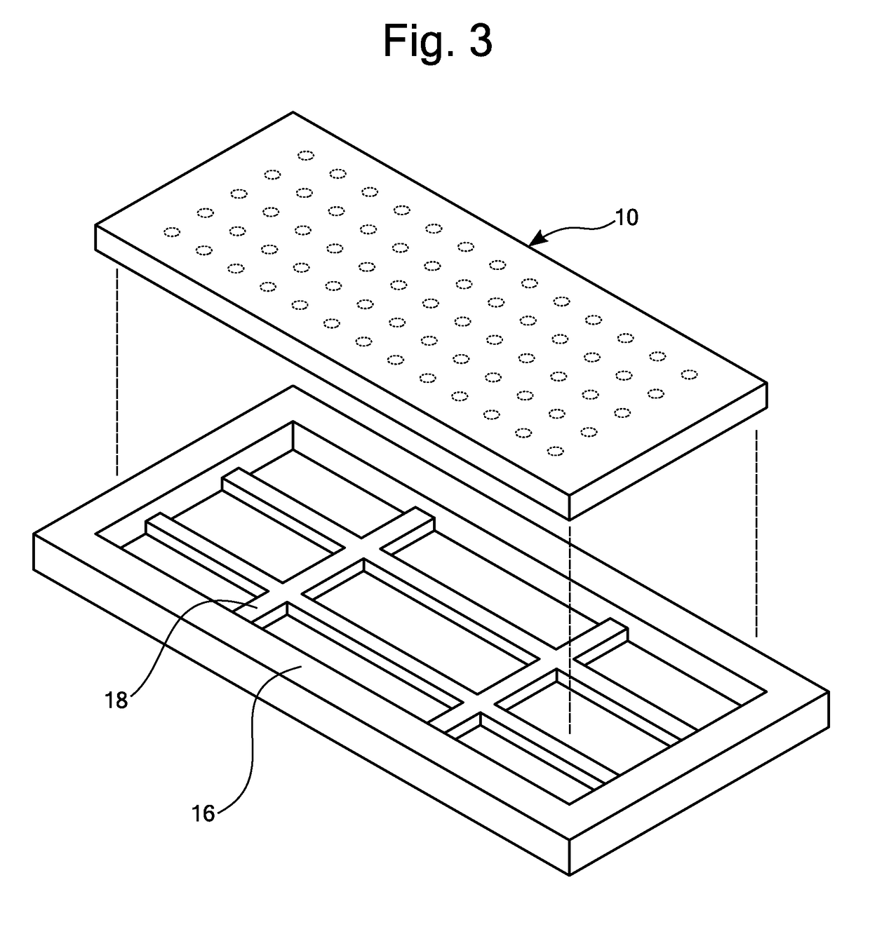
The invention provides a hardness testing block with a properly aligned template and a cradle that protects the test surface from damage during testing. This allows for efficient and safe testing of hard materials.

Problems solved by technology

That is, when using a fixed force (load) on a particular indenter, the smaller the indentation, the harder the material.
Therefore, the cost of the material per indentation allowed is a large component of the total cost of producing these test blocks.
This block using prior art layouts methods of test sites can only accommodate 65 test sites per block.
There are several issues with the current test blocks being offered.
As noted above, the number of test sites per block is limited due to the spacing requirements.
While test blocks are typically laid out with a grid pattern to indicate the proper spacing and location of the test sites, an operator who fails to properly line up with the test block with the hardness testing machine even by a small amount, the spacing between subsequent tests cannot be maintained and even less tests can be utilized.
This is difficult when using current methods.
Finally, there is no method for optimizing the test sites patterns on a given size test block for a particular indentation size (corresponding to a particular hardness).
With the current grid imprinting available on some test blocks, it is still possible to place indentation inside the marked area and still not meet the spacing requirements.

Method used


Image

  • Method and apparatus for a hardness test block
  • Method and apparatus for a hardness test block
  • Method and apparatus for a hardness test block

Examples


Embodiment Construction

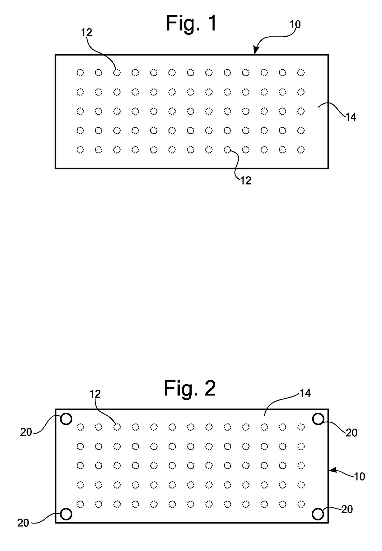
[0025]Shown in FIG. 1, is a typical Brinell 2.5 inch by 6 inch test block 10 showing the grid pattern of 65 test sites 12, with each site accommodating a 3.5 mm expected diameter indentation and meeting ASTM spacing requirements. Note that this layout does not use the staggered method of laying out test sites using a staggered technique that can provide a greater number of test sites for the same sized test block. (See U.S. Pat. No. 3,352,148, issued to Johnson on Nov. 14, 1967.) However, the techniques and methods described herein can also be applied to test blocks having a staggered pattern as disclosed by Johnson.

[0026]All of test sites 12 are provided on surface 14. The layout of sites 12 can be shown inscribed on surface 14 by being imprinted or etched on surface 14 or surface 14 can be left blank. However, due to the ASTM spacing requirements, the number of test sites is limited irrespective of whether surface 14 is marked with the location of the test sites or left blank. Als...


PUM


Abstract

A hardness test block wherein the number of test sites is optimized for a given test block size and a hardness being tested. The hardness test block has an alignment template that enables an operator to be assured of having the test bock grid pattern aligned properly with the indenter of a hardness testing machine. Another means for aligning the test block with the hardness testing apparatus is a cradle for the test block so that the primary test surface as well as the opposite surface can both be used for testing purposes such that the cradle protects the test surface from being contacted by the anvil of the hardness testing machine during the test operation. Another alternative is having a plurality of legs or pins on the test surface of the test block to prevent the test surface from contacting the anvil when the opposite test surface is being used for testing. A formula is provided so that the optimum grid pattern for a test surface can be obtained for any test block, irrespective of size, shape, or expected indentation size in order to obtain the least amount of test block material needed for a given number of test sites.

Description

[0001]This application claims benefit of U.S. Provisional Application Ser. No. 62 / 279,813 filed Jan. 17, 2016 pursuant to 25 USC §119(e).FIELD OF THE INVENTION[0002]This invention relates to hardness testing equipment and methods, in particular, test blocks for checking the accuracy of the hardness measuring equipment.BACKGROUND OF THE INVENTION[0003]Indentation testing is very widely used in the industry for the determination of metal hardness. Hardness is a characteristic of a material, not a fundamental physical property. It is defined as the resistance to indentation, and it is determined by measuring the permanent depth of the indentation or its diameter. That is, when using a fixed force (load) on a particular indenter, the smaller the indentation, the harder the material. Indentation hardness value is obtained by measuring the depth or the area of the indentation using one of over 12 different test methods.[0004]One of the most common methods of determining hardness is the Br...

Claims


Application Information

Patent Timeline
IPC IPC(8): G01N3/42G01B11/28G01N3/40G01B11/02
CPCG01N3/42G01B11/022G01N2203/008G01N3/40G01B11/285G01N2203/021G01N2203/027
Inventor MAZZOLENI, GIANCARLOMAZZOLENI, CARLO
Owner MAZZOLENI GIANCARLO
Learn More