Resonator and optical sensor using the same
a resonator and optical sensor technology, applied in the field of resonators and optical sensors, can solve the problems of reducing the q-factor of the resonator, the inability of the optical sensor using the typical resonator to perform measurement, and the limitation of commercialization, so as to achieve simple manufacturing and driving, high resolution, and high sensitivity
- Summary
- Abstract
- Description
- Claims
- Application Information
AI Technical Summary
Benefits of technology
Problems solved by technology
Method used
Image
Examples
first embodiment
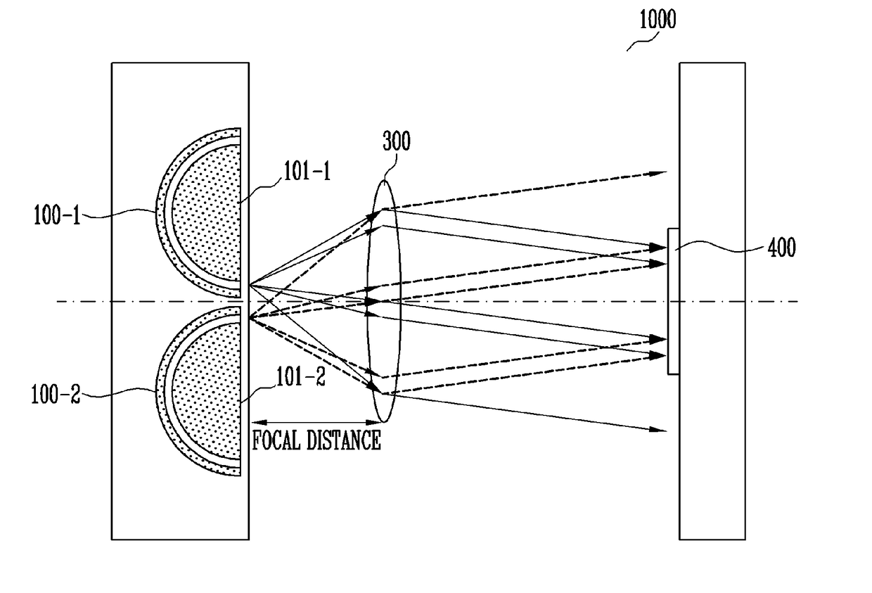
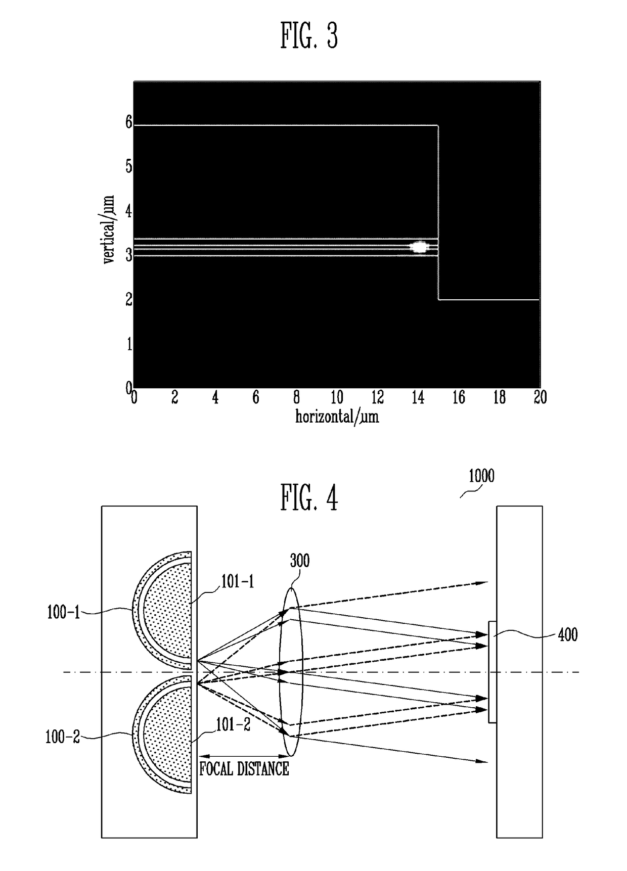
[0048]FIG. 4 is a view showing a structure of an optical sensor according to the present disclosure.
[0049]Referring to FIG. 4, the optical sensor 1000 according to the first embodiment of the present disclosure has a structure in which first and second resonator 100-1 and 100-2 according to the present disclosure are aligned in parallel such that cutting planes 101-1 and 101-2 face in the same direction. More specifically, the first and second resonator 100-1 and 100-2 are aligned such that the cutting planes 101-1 and 101-2 face an optical detector 400 which will be described later.
[0050]The aligned first and second resonators 100-1 and 100-2 are provided at a focal distance of a lens 300. The optical detector 400 is provided at the opposite side of the first and second resonators 100-1 and 100-2 with respect to the lens 300. The optical detector 400 may be provided at a position at which, as will be described below, beams that are output from the first and second resonators 100-1 ...
second embodiment
[0054]FIG. 6 is a view showing a structure of an optical sensor according to the present disclosure.
[0055]Referring to FIG. 6, as compared with the optical sensor 1000 according to the first embodiment, the optical sensor 3000 according to the second embodiment of the present disclosure may include, instead of the lens 300, first and second distributed Bragg reflectors (hereinafter, referred to as DBRs) 500-1 and 500-2 and a Y-shaped coupler 600.
[0056]In the optical sensor 3000 according to the second embodiment of the present disclosure, the first and second DBR 500-1 and 500-2 are integrated such that the cutting plane 101-1 or 101-2 of one of the first and second resonators 100-1 and 100-2 is etched down to the substrate 140, thereby forming a reflection plane, and the cutting plane 101-1 or 101-2 of the other of the first and second resonators 100-1 and 100-2, which detects output beams performs reflection caused by the DBRs, instead of reflection caused by etching. Beams output...
third embodiment
[0059]FIG. 7 is a view showing a structure of an optical sensor according to the present disclosure.
[0060]Referring to FIG. 7, as compared with the optical sensor 3000 according to the second embodiment, the optical sensor 4000 according to the third embodiment of the present disclosure may include directional couplers 700-1 and 700-2, instead of the Y-shaped coupler 600.
[0061]In various embodiments, the directional couplers 700-1 and 700-2 may be formed as shallow ridge waveguides. Here, the shallow ridge waveguides have a length for achieving optical coupling that is about 50% with respect to beams output from the first and second resonators 100-1 and 100-2, and may be disposed at a distance for achieving the optical coupling.
[0062]The directional couplers 700-1 and 700-2 are integrated at ends of the first and second diffraction grids 500-1 and 500-2. At this time, beating signals of beams are output from first and second waveguides 700-1 and 700-2 of the directional couplers 700...
PUM
 Abstract
Description
Claims
Application Information
 - R&D
- Intellectual Property
- Life Sciences
- Materials
- Tech Scout
- Unparalleled Data Quality
- Higher Quality Content
- 60% Fewer Hallucinations
Browse by: Latest US Patents, China's latest patents, Technical Efficacy Thesaurus, Application Domain, Technology Topic, Popular Technical Reports.
© 2025 PatSnap. All rights reserved.Legal|Privacy policy|Modern Slavery Act Transparency Statement|Sitemap|About US| Contact US: help@patsnap.com


