
Operation device

a technology of operation device and trigger, which is applied in the direction of mechanical control device, gearing, instruments, etc., can solve the problems of difficult to perform a realistic game operation, the vibration applied to the entire gun is not easily transmitted to the trigger, and the difficulty of adjusting the trigger position, etc., to achieve the effect of reducing the size and weight of the chassis and high accuracy

Active Publication Date: 2017-07-27
ALPS ALPINE CO LTD
View PDF0 Cites 3 Cited by
  • Summary
  • Abstract
  • Description
  • Claims
  • Application Information

AI Technical Summary

Benefits of technology

The present invention provides an operation device that reduces rattling and improves operational smoothness. The guide structure reduces rattling and allows the operator to feel a direct reaction force acting on the operation portion. The guide shaft and bearing portion of the movement member moving along it easily prevent rattling and allow for smooth pressing. The operation reaction force easily acts on the hand or finger operating the operation portion. The thin profile of the movement device is enabled by a combination of a thin chassis and efficient force transmission between the movement member and the pinion gear. The movement member moves forward and rearward with high accuracy without rattling.

Problems solved by technology

Since the gun unit disclosed in Japanese Unexamined Patent Application Publication No. 7-24147 provides forward and rearward reciprocations with respect to the entire gun main body and does not directly give a reaction feeling to a finger operating the trigger, it is difficult to perform a realistic game operation.
In addition, since the reaction force which is applied to the gun main body is limited to a vibration force due to a rotation of a motor, it is not possible to give various operation reaction forces to an operator.
In addition, if slight rattling is generated in the trigger, vibrations applied to the entire gun are not easily transmitted to the trigger, and it is difficult to realize a more realistic game operation.

Method used


Image

  • Operation device
  • Operation device
  • Operation device

Examples


Embodiment Construction

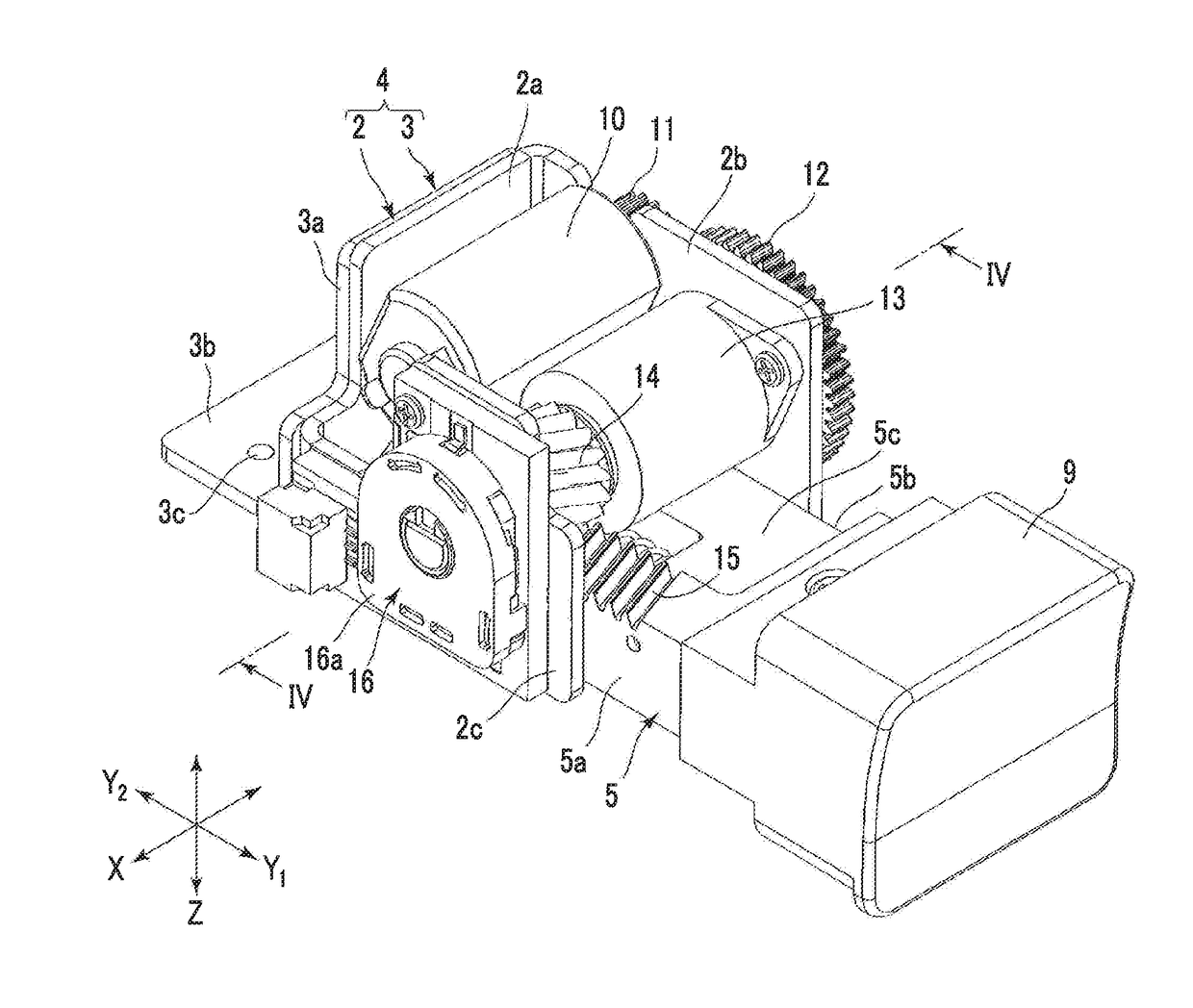
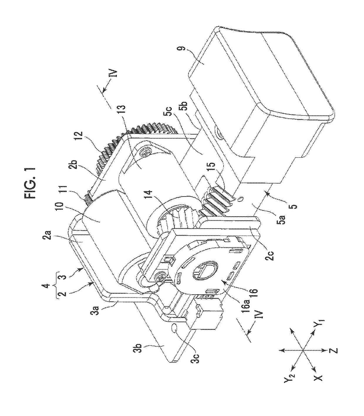
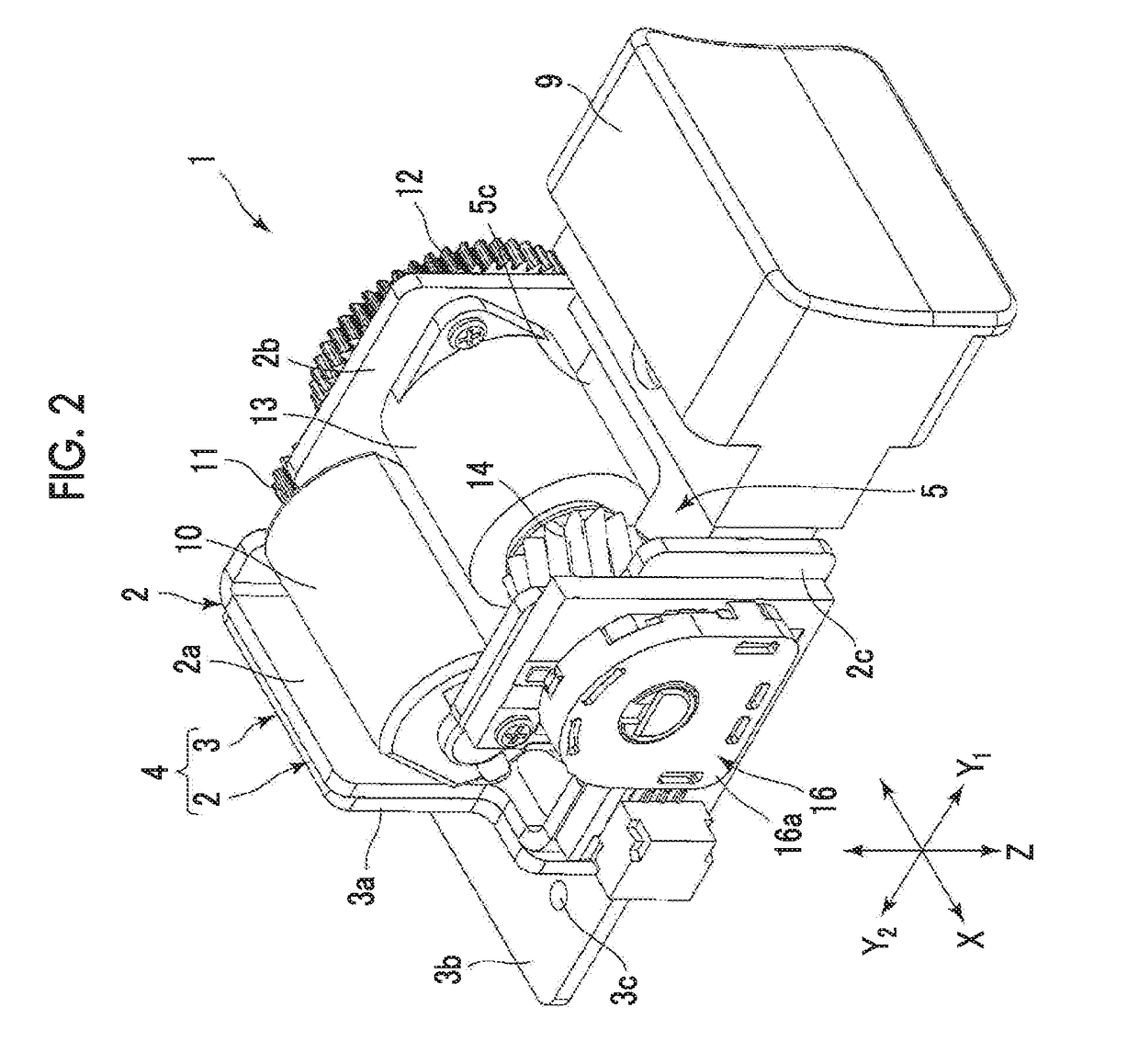
[0033]FIGS. 1 to 7 show an example in which an operation device according to an embodiment of the present invention is mounted on a gun-type controller for a shooting game. However, as described later, the operation device of the present invention can be mounted on various controllers other than the gun-type controller and various devices applied to those other than games.

[0034]In an operation device 1 shown FIGS. 1 to 4, an X direction is a horizontal direction, a Y direction is a forward-rearward direction, and a Z direction is a vertical direction. The operation device 1 includes a chassis 4. The chassis 4 is configured of a main body frame 2 and a bracket 3 for fixing the main body frame inside the gun-type controller. Both the main body frame 2 and the bracket 3 are formed of a sheet metal material.

[0035]The main body frame 2 includes a facing wall portion 2a, and a first side wall portion 2b and a second side wall portion 2c which are perpendicularly bent from both side portio...


PUM


Abstract

A movement member which reciprocates includes a thick portion and a thin portion, a bearing portion formed in the thick portion is slidingly supported by the guide shaft, and a sliding portion formed in the thin portion is slidingly guided by the sliding guide portion. Power of the motor is transmitted to a pinion gear via a speed reduction gear and a speed reduction mechanism inside a gear box, and a movement reaction force is applied from the pinion gear to the rack portion. Since the rack portion is positioned on an axis Os, a force is effectively applied to the movement member by the power from the motor.

Description

CLAIM OF PRIORITY[0001]This application is a Continuation of International Application No. PCT / JP2015 / 078287 filed on Oct. 6, 2015, which claims benefit of Japanese Patent Application No. 2014-224741 filed on Nov. 4, 2014. The entire contents of each application noted above are hereby incorporated by reference.BACKGROUND OF THE INVENTION[0002]1. Field of the Invention[0003]The present invention relates to an operation device which presses and operates an operation portion by hand, and particularly, to an operation device which can control a reaction force acting on an operation portion according to an operation position of the operation portion.[0004]2. Description of the Related Art[0005]An operation device to which a reaction force is applied when an operation portion is operated is widely used as a controller for a game device.[0006]Japanese Unexamined Patent Application Publication No. 7-24147 discloses an invention relating to a gun unit used in a shooting game device as a cont...

Claims


Application Information

Patent Timeline
Patent Type & Authority Applications(United States)
IPC IPC(8): G05G5/03H02K11/21H02K7/06H02K7/116F16H19/04G05G1/02
CPCG05G5/03F16H19/04H02K11/21H02K7/06H02K7/116G05G1/02G06F3/016G06F3/0202G06F3/0362A63F13/24A63F13/28A63F13/285
Inventor SATO, KUNIOMIYAZAKI, SHUNHAGIWARA, YASUJIWAKANA, KEIGOSAKURAI, SHOJI
Owner ALPS ALPINE CO LTD
Learn More