
Self Testing GFCI

a self-testing, circuit-interrupting technology, applied in the direction of protective switch details, instruments, signalling systems, etc., can solve the problems of reducing affecting the safety of users, so as to reduce the number of instances of nuisance tripping

Active Publication Date: 2017-07-27
CARLING TECH
View PDF0 Cites 5 Cited by
  • Summary
  • Abstract
  • Description
  • Claims
  • Application Information

AI Technical Summary

Benefits of technology

The patent describes a self-testing GFCI device that reduces the number of instances of nuisance tripping while complying with UL-943 standards. The device can be used in either a single phase or two phase application. The device measures the falling edge pulse and injects the self-test signal at a point above 50% amplitude on the falling edge for better accuracy. This method eliminates potential interference with the self-test signal and reduces the sensitivity to power frequency variations. Overall, the device provides a more reliable and efficient means of testing for safety compliance.

Problems solved by technology

Although the widespread use of GFCI devices for the past thirty-plus years has led to a large number of installations, these devices are susceptible to deterioration and eventual failure.
Failure of the GFCI device can lead to the device providing electrical power like any normal circuit breaker or outlet, even though the protective features that differentiate the GFCI device from conventional devices is no longer functional.
This creates a dangerous situation where the GFCI device is still viewed as functional and providing life safety protection when, in fact, it is not.
When a user pushes the test button, this simulates a problem such that the outlet should toggle to a tripped or open state to interrupt the supply of electrical power to the “load” terminals and to the any device plugged into the outlet.
However, it has been shown that most individuals do not regularly test the GFCI outlets or circuit breakers in their homes to ensure that they are functioning correctly.
Likewise, even in commercial applications, the GFCI devices are rarely tested.
This leads to the dangerous situation that GFCI devices that are currently in service are not functioning to provide the protection intended but are still in service as they continue to provide electrical power.
A challenge faced by manufacturers is how to perform the self-testing automatically without impacting the normal function and the operation of the GFCI device.
In other words, the GFCI device must be tested on a regular basis to determine if it is still operational, however, this self-testing cannot interfere with the tripping of the GFCI device in the event that an actual ground fault occurred.
If, during the self-test, it is determined that the GFCI device is no longer functional, the device must either deny power or provide a visual and / or audible indication that the device is no longer functioning properly.
However, a major problem with previously known designs is that they suffer from nuisance tripping.
However, a major drawback to the design of the '174 patent relates to the methodology of injecting the test pulse into the device.
A challenge that manufacturers face is how to inject the test pulse into the device without interfering with other signals present in the device.
This method is relatively effective in avoiding the charging cap in the second quadrant, however, as the signal is shifted relatively late in the fourth quadrant, there is the propensity that interference could occur with the next half wave.

Method used


Image

  • Self Testing GFCI
  • Self Testing GFCI
  • Self Testing GFCI

Examples


Embodiment Construction

[0032]Referring now to the drawings, wherein like reference numerals designate corresponding structure throughout the views.

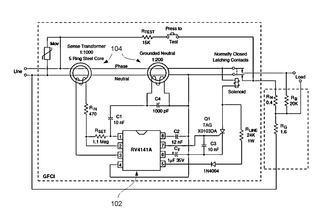
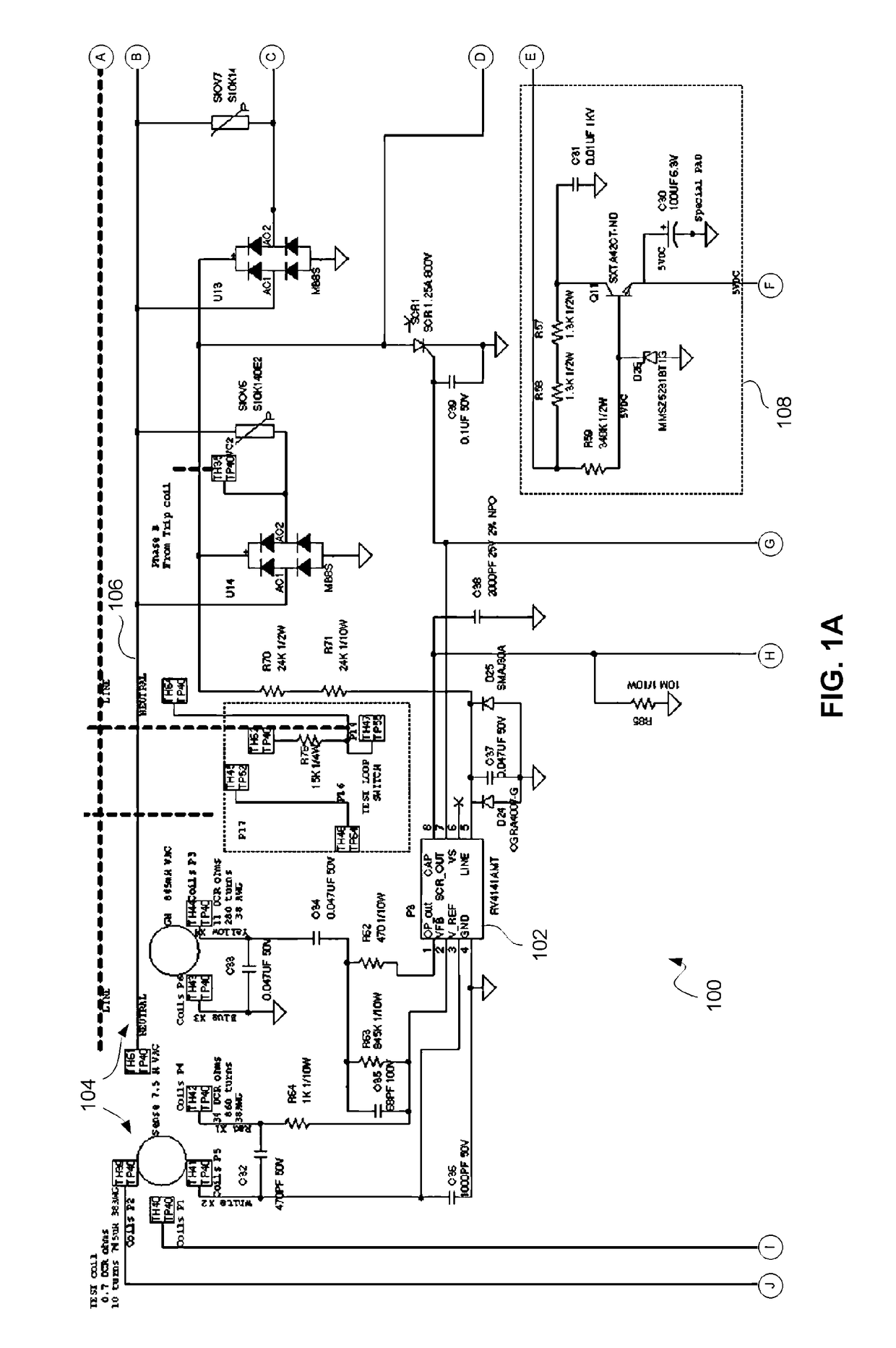
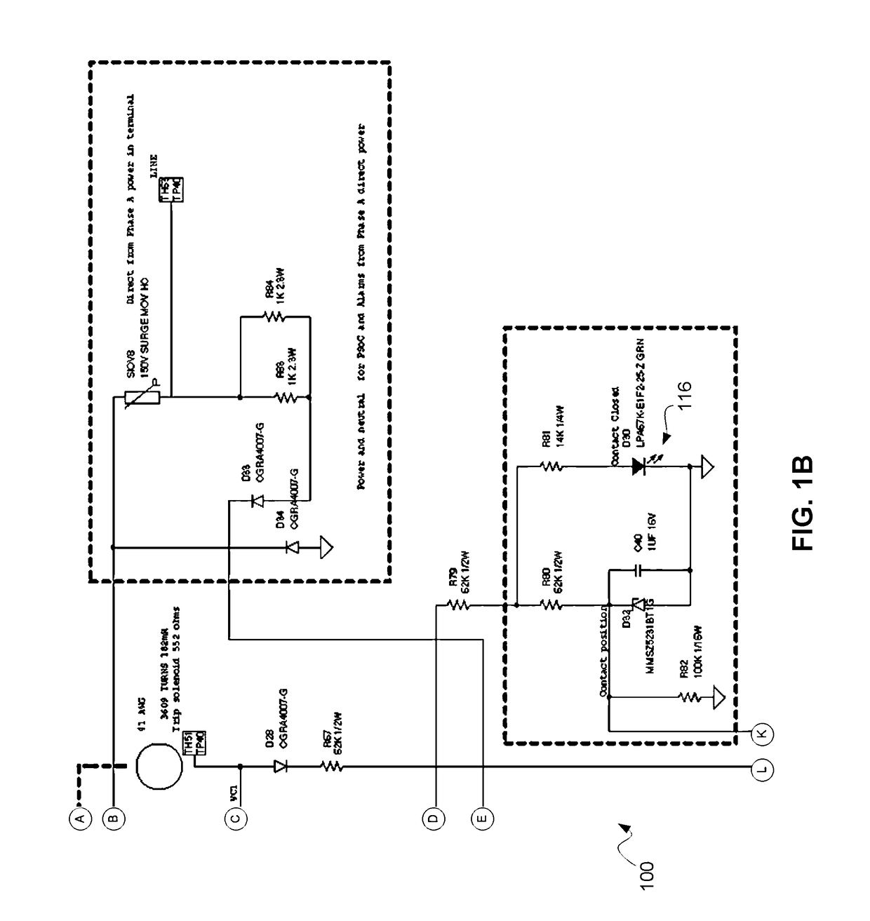
[0033]Referring now to FIGS. 1A-1C a schematic diagram illustrating a circuit configuration of the circuit interrupter 100. The schematic diagram is provided into three parts on FIGS. 1A through 1C where the circles with letters indicate circuit connections between FIGS. For example, on the right hand side of FIG. 1A the designations A-E are each shown inside a circle. The corresponding connections for designations A-E are shown on the left hand side of FIG. 1B where “A” in FIG. 1A is a connection to “A” in FIG. 1B and so on. Likewise, FIG. 1A shows designations F-J on the bottom of the page and corresponding designations F-J are shown at the top of FIG. 1C indicating the circuit connections. Finally, the designations K-L are shown at the bottom of FIG. 1B with corresponding designation K-L shown at the top of FIG. 1C indicating the circuit connections.

[0034]A ...


PUM


Abstract

A self-testing circuit interrupting device including Ground Fault Circuit Interrupter protection, the circuit interrupting device usable with single phase power where a test pulse is injected into a falling edge of the electrical signal at a point greater than 54.2% of the maximum amplitude of the electrical signal. The circuit interrupting device usable with dual phase power where the test pulse is injected into a falling edge of the electrical signal at 0.879 ms from a minimum amplitude of the electrical signal.

Description

FIELD OF THE INVENTION[0001]The present invention relates to a self-testing circuit interrupting device including a Ground Fault Circuit Interrupter (GFCI).BACKGROUND OF THE INVENTION[0002]A GFCI is a device that is capable of switching between a tripped (open) and an operative (closed) condition based on the detection of selected criteria. Specifically, a GFCI device is designed to interrupt the supply of electric power when the device detects that current is traveling along an unintended path (e.g., through a person, or through water, etc.). GFCI devices may be included in any of numerous types of components that are capable of interrupting the supply of electric power, such as arc fault interrupters, circuit breakers, electrical outlets, etc.[0003]GFCI outlets and circuit breakers have become widely used throughout the United States and are credited with saving many lives. Although the widespread use of GFCI devices for the past thirty-plus years has led to a large number of inst...

Claims


Application Information

Patent Timeline
IPC IPC(8): H01H83/04G08B5/36H01H71/04
CPCH01H83/04H01H2071/044G08B5/36H01H71/04H01H83/144H02H3/335G01R31/3275G01R31/3277G01R31/327
Inventor SIMONIN, STEPHEN P.
Owner CARLING TECH
Learn More