
Aspiration thrombectomy system and methods for thrombus removal with aspiration catheter

a thrombus and catheter technology, applied in balloon catheters, medical science, surgery, etc., can solve the problems of brain damage or death, brain cells begin to die, and the cost of removing a clot is significant, so as to reduce the instance of aspiration catheters and increase the first-pass recanalization rate

Active Publication Date: 2020-01-23
RAPIDPULSE INC
View PDF0 Cites 24 Cited by
  • Summary
  • Abstract
  • Description
  • Claims
  • Application Information

AI Technical Summary

Benefits of technology

The system effectively removes clots without clogging, confirms complete aspiration, and significantly increases first-pass recanalization rates by preventing forward flow and ensuring complete clot retrieval, reducing procedure time and complications.

Problems solved by technology

Within minutes, brain cells begin to die, which, if not treated rapidly, causes brain damage or death.
The costs associated with removing a clot are significant.
Conceptually, aspiration is effective but some significant problems occur in practice.
The other option is not viable, that is, reversing the suction to pressurize the clot and eject it forcibly and uncontrollably out of the distal opening of the aspiration catheter.
Such action is dangerous to the patient for many reasons, the primary one being that forcibly and uncontrollably ejecting the clot may cause the clot to move further distally within the vessel in which it was originally lodged.
That distal movement would not only cause the clot to be further within the vessel—i.e., in an even smaller diameter of the vessel than when it was originally lodged—but it could permanently lodge the clot into that vessel, making it impossible to remove, or it could burst the vessel.
Even when the surgeon uses the aspiration catheter to fish out the clot, there is no assurance that the entirety of the clot will be removed.
Pieces of the clot can break off during movement, when that occurs, the pieces re-embolize within the same vessel or within different vessels that might be even more difficult to remove.
When all or most of the clot is drawn out from the patient, it is difficult to confirm that the entire thrombus was removed.
A significant disadvantage of current thrombus removal devices is the inability of a surgeon to ascertain thrombus capture / removal without the full withdrawal of a given therapeutic device from a patient's anatomy.
Even systems capable of fully aspirating a given thrombus are problematic, because the reservoirs into which aspirated contents are deposited are located outside of the sterile field in an operating room setting.
This location, outside the sterile field, makes it difficult or impossible for physicians operating aspiration catheters to easily visualize and appraise aspirated thrombus material.
The aspiration and balloon guide catheters have to be cleaned out, access to distal anatomy has to be re-established, and, when the aspiration catheter finally is located back at the embolism site, the same issues may be present again with whatever embolus material remains.
A disadvantage of these procedures is the significant increase in procedure time, which not only significantly increases the cost (as each minute in an operating room is expensive), it also increases the surgeon's stress, which decreases the success rate of the operation.
Even with an attempt to maintain vacuum pressure utilizing manual periodic cycling, prior art systems are not capable of avoiding positive pressures at the distal end of the catheter.
Prior art systems are not able to react quickly enough to keep the distal end of the catheter from experiencing a positive pressure.
The prior art do not have a fast enough reaction time to quell forward flow.
Such systems cannot guarantee removing all forward flow eliminating positive pressure at the distal end of the catheter.

Method used


Image

  • Aspiration thrombectomy system and methods for thrombus removal with aspiration catheter
  • Aspiration thrombectomy system and methods for thrombus removal with aspiration catheter
  • Aspiration thrombectomy system and methods for thrombus removal with aspiration catheter

Examples


Embodiment Construction

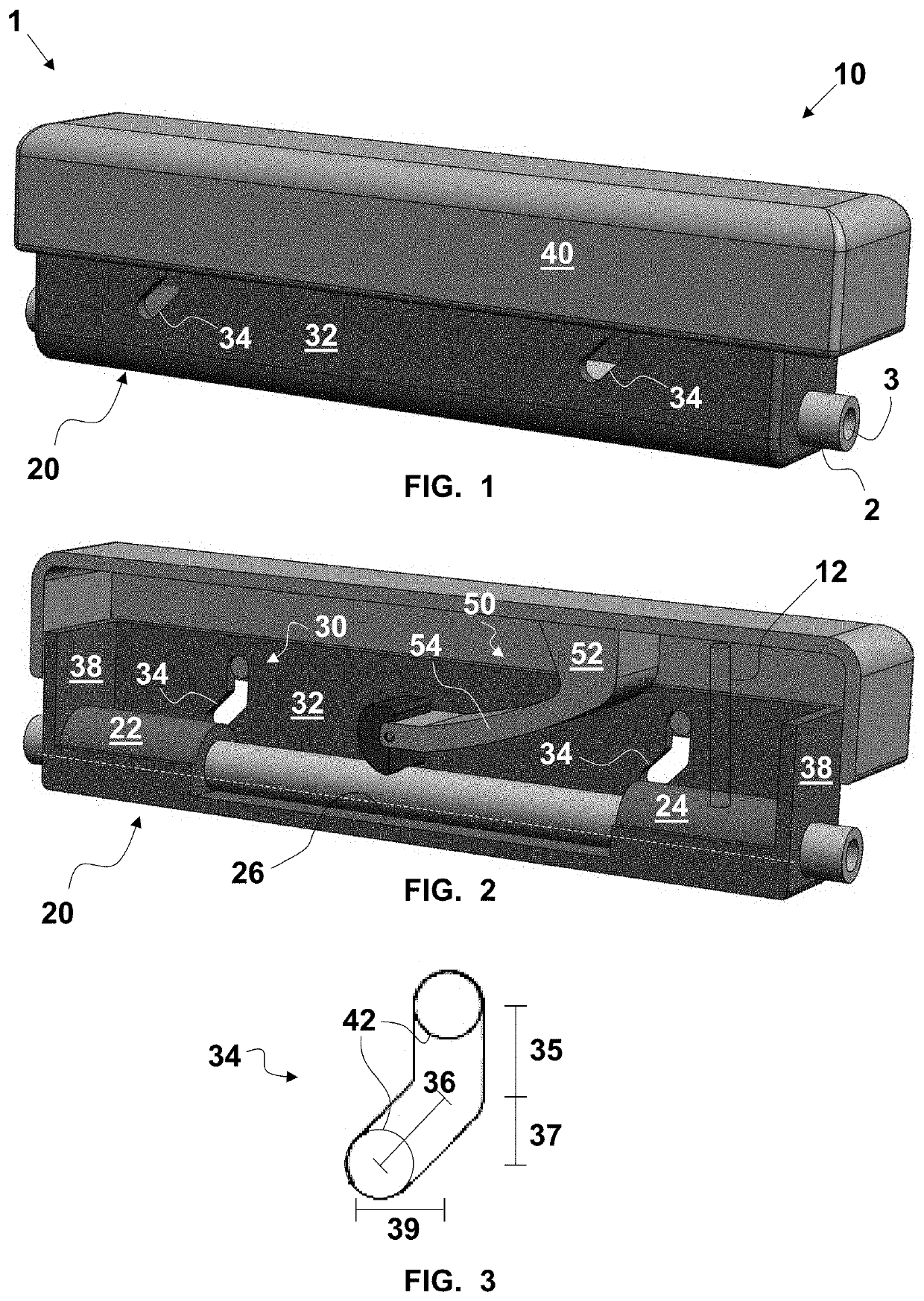
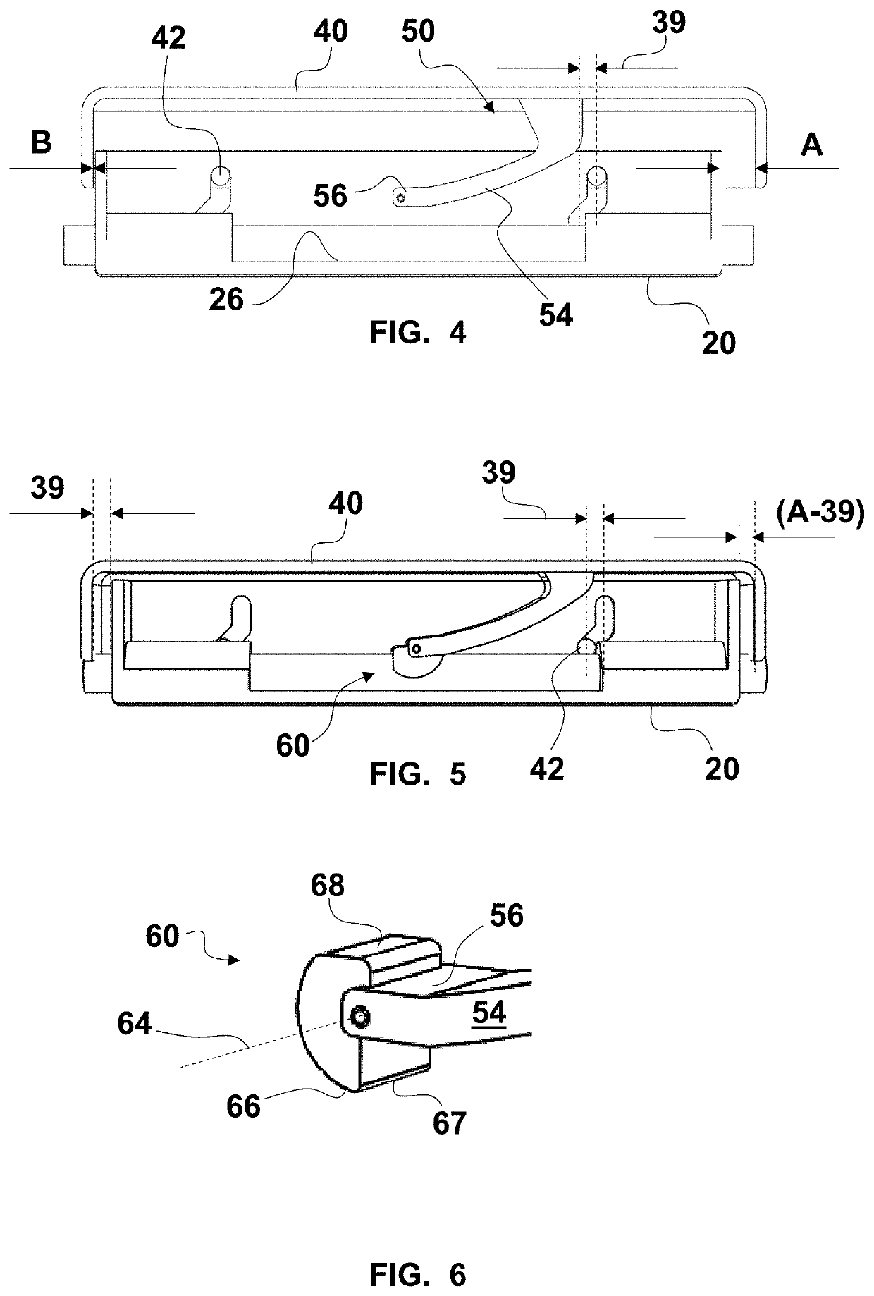
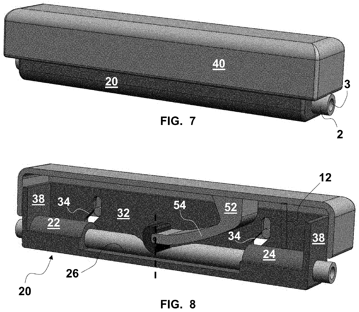
[0137]As required, detailed embodiments of the systems, apparatuses, and methods are disclosed herein; however, it is to be understood that the disclosed embodiments are merely exemplary of the systems, apparatuses, and methods, which can be embodied in various forms. Therefore, specific structural and functional details disclosed herein are not to be interpreted as limiting, but merely as a basis for the claims and as a representative basis for teaching one skilled in the art to variously employ the systems, apparatuses, and methods in virtually any appropriately detailed structure. Further, the terms and phrases used herein are not intended to be limiting; but rather, to provide an understandable description of the systems, apparatuses, and methods. While the specification concludes with claims defining the features of the systems, apparatuses, and methods that are regarded as novel, it is believed that the systems, apparatuses, and methods will be better understood from a conside...


PUM


Abstract

A thrombectomy removal system includes a catheter having a distal end and defining a lumen filled with a liquid column having a proximal portion and a distal portion, a vacuum source, a vent liquid source, and a vacuum and vent control system configured to cyclically connect or disconnect the vacuum source and the vent liquid source to change a level of vacuum at the distal end and substantially prevent forward flow. The vacuum source and the vent source are respectively fluidically connected to the vacuum and vent valves. A manifold connects the proximal portion to the vacuum and vent sources through the valves. Control of the valves prevents forward flow of the distal portion out from the distal end during each cycle. Each cycle can have states including vacuum-only, first double-closed, vent-only, and second double-closed. A time of the double-closed states can be no greater than 30 ms.

Description

CROSS-REFERENCE TO RELATED APPLICATIONS[0001]This application claims the priority, under 35 U.S.C. § 119, of copending U.S. Provisional Patent Application Nos. 62 / 701,086, filed Jul. 20, 2018, and 62 / 750,011, filed Oct. 24, 2018; the prior applications are herewith incorporated by reference herein in their entirety.STATEMENT REGARDING FEDERALLY SPONSORED RESEARCH OR DEVELOPMENT[0002]Not ApplicableFIELD OF THE INVENTION[0003]The present systems, apparatuses, and methods lie in the field of thrombus removal. The present disclosure relates to an aspiration thrombectomy system and methods for thrombus removal with aspiration catheter.BACKGROUND OF THE INVENTION[0004]Ischemic strokes are usually caused by a blood clot that blocks or plugs a blood vessel in the brain. This blockage prevents blood from flowing to the brain. Within minutes, brain cells begin to die, which, if not treated rapidly, causes brain damage or death. The costs associated with removing a clot are significant. Most t...

Claims


Application Information

Patent Timeline
Patent Type & Authority Applications(United States)
IPC IPC(8): A61B17/22A61M25/00A61F2/01
CPCA61B2217/007A61B2017/00022A61B17/22A61M25/0075A61F2/013A61B2017/22079A61B2217/005A61B2017/00154A61M2210/0693A61M25/00A61M25/10A61M1/742A61M1/75A61M1/74A61M1/743A61M1/79A61B2017/22082A61F2/011
Inventor DEVILLE, DEREK DEEPALMER, MATTHEW A.BALES, JR., WILLIAM T.MCBRAYER, M. SEANPETERSEN, ERICCARTLEDGE, RICHARD
Owner RAPIDPULSE INC
Learn More