

Substrate processing apparatus and substrate processing method
- Summary
- Abstract
- Description
- Claims
- Application Information
AI Technical Summary
Benefits of technology
Problems solved by technology
Method used
Image

Examples
second embodiment
[0050]As shown in FIG. 7, a peripheral edge solidifier 40 employed in the second embodiment includes a rotary shaft 41 configured to be rotatable about a vertical axis AX2, an arm 45 extending in a horizontal direction from the rotary shaft 41, a contact member 46 mounted on the tip of the arm 45 while being faced down, a Peltier element 47 (FIG. 8) mounted on the contact member 46 and a rotating / elevating mechanism 48 (FIG. 8) for rotating the arm 45. In the embodiment, the rotating / elevating mechanism 48 drives and rotates the rotary shaft 41 in response to a rotation command from a control unit 90, whereby the arm 45 swings about the vertical axis AX2, which causes the contact member 46 to reciprocally move between a retracted position outside a splash guard 30 and a position where the contact member 46 faces a peripheral edge part of a substrate W (corresponding to the “second position” of the invention) P2 (FIG. 7). Further, the rotating / elevating mechanism 48 drives and raises...
first embodiment
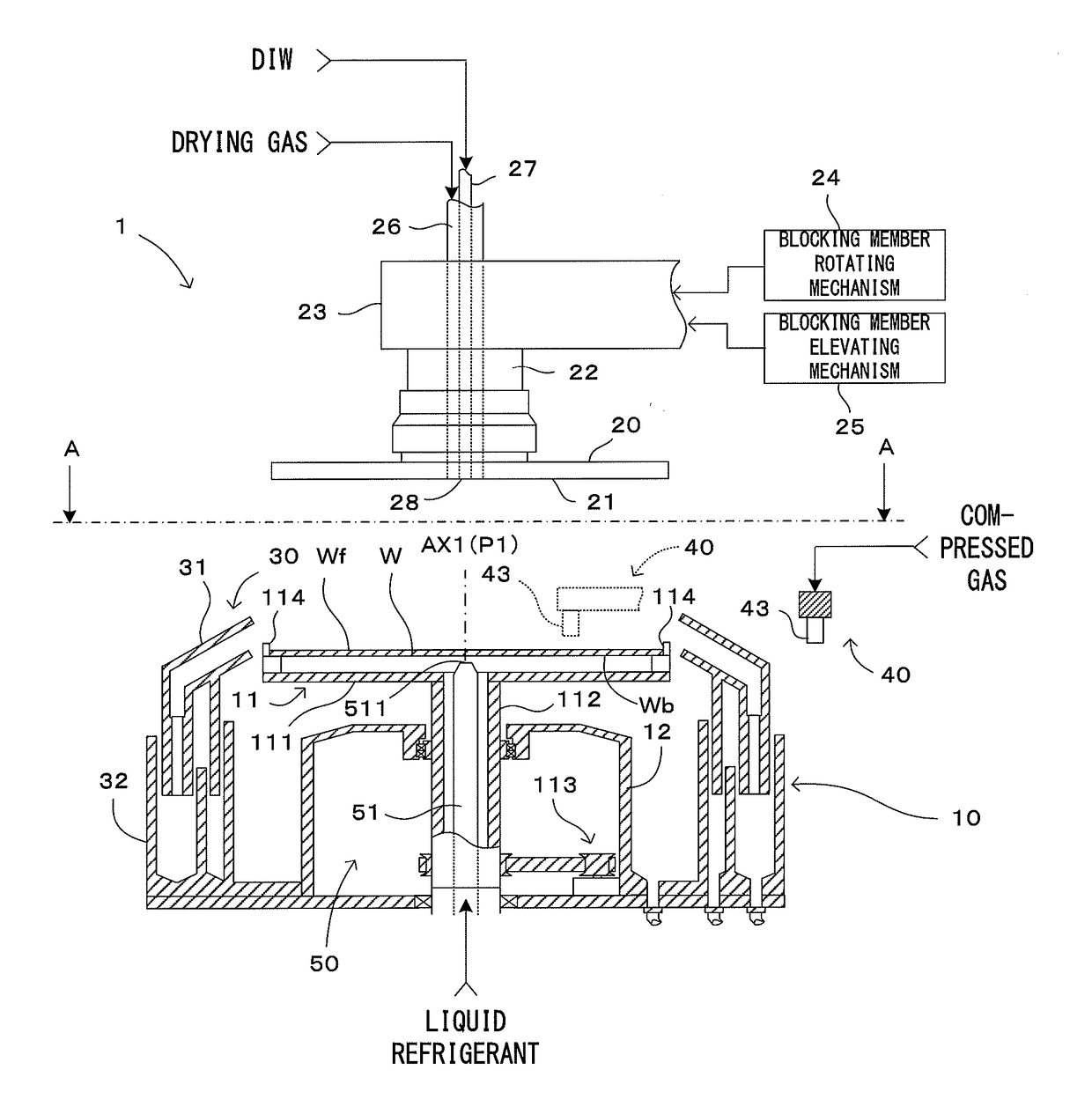
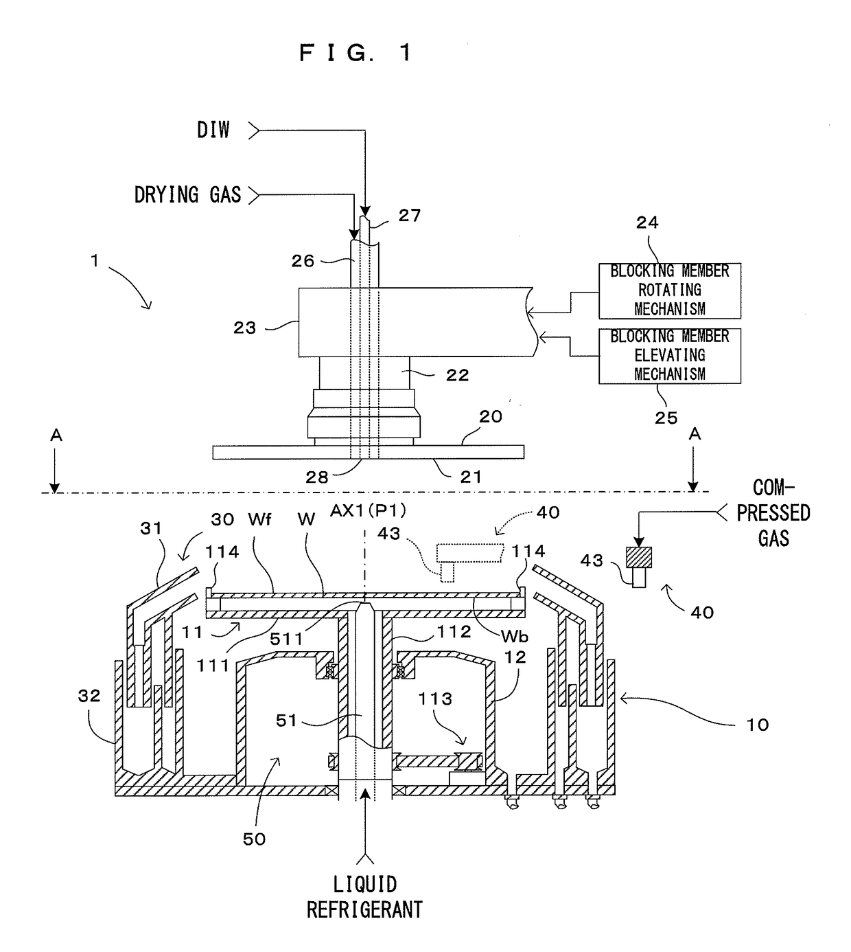
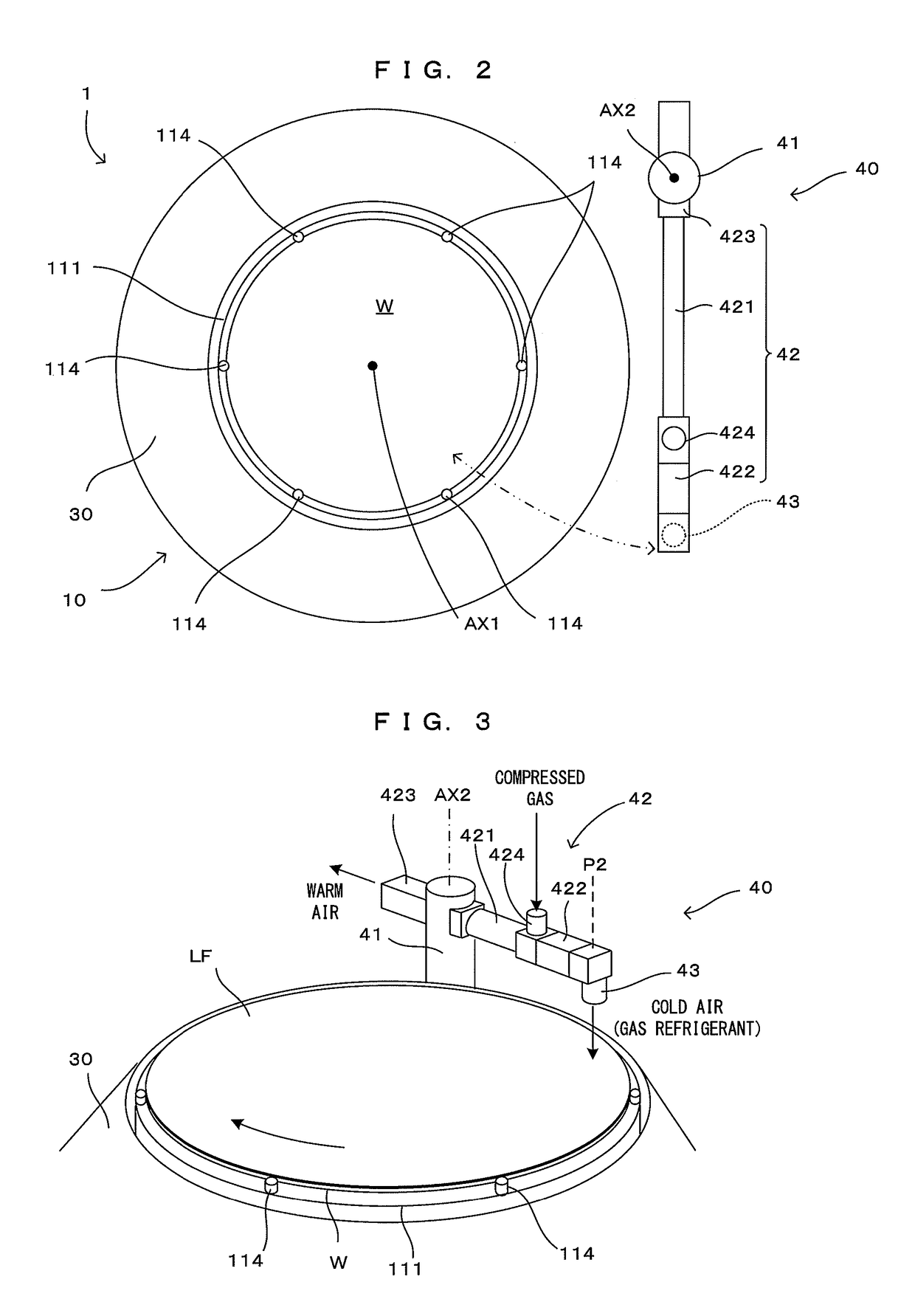
[0060]Further, although the cold air is supplied to the front surface Wf of the substrate W vertically from above in the first embodiment, a cold air supplying direction is not limited to this as long as cold air is supplied to the liquid film LF located at the position P2. For example, the peripheral edge part of the liquid film LF may be solidified by supplying cold air to the back surface Wb of the substrate W at the position P2. Further, cold air may be supplied obliquely from above or below. Further, although the position P1 is matched with the axis of rotation AX1 in the above embodiments, a position deviated from the axis of rotation AX1 in the radial direction of the substrate W may be set as the position P1.
[0061]Further, although the cold air is supplied in the first embodiment and the lower surface 461 of the contact member 46 is brought into contact with the liquid in the second embodiment to solidify the liquid film LF located on the peripheral edge part of the front su...
PUM
 Abstract
Description
Claims
Application Information