Anti-icing system and aircraft

a technology of anti-icing system and aircraft, which is applied in the direction of aircraft components, transportation and packaging, de-icing equipment, etc., can solve the problems of insufficient heating, damage to the leading edge structure, and accelerated overheating, so as to achieve efficient ejecting of bleed air

Active Publication Date: 2017-08-03
MITSUBISHI AIRCRAFT
View PDF0 Cites 15 Cited by
  • Summary
  • Abstract
  • Description
  • Claims
  • Application Information

AI Technical Summary

Benefits of technology

[0023]According to the present invention, it is possible to efficiently eject the bleed air from the ejection holes towa

Problems solved by technology

If the positions of the respective ejection holes of the piccolo tube are not appropriate, disadvantageously, heating may become insufficient or damage of the leading edge structure caused by overheating may be accelerated.
When the flight condition, in particular, an angle of attack of the aircraft is varied and the position of the stagnation point is accordingly moved, however, the blown point, namely, a point to which the heating amount is concentrated is not coincident with the position at which the collision amount of the droplets shows a peak as illustrated in FIG. 10C, which deteriorates efficiency o

Method used


Image

  • Anti-icing system and aircraft
  • Anti-icing system and aircraft
  • Anti-icing system and aircraft

Examples


first embodiment

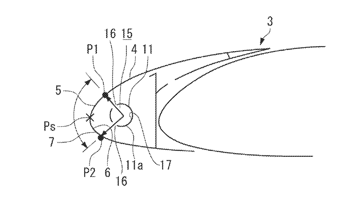
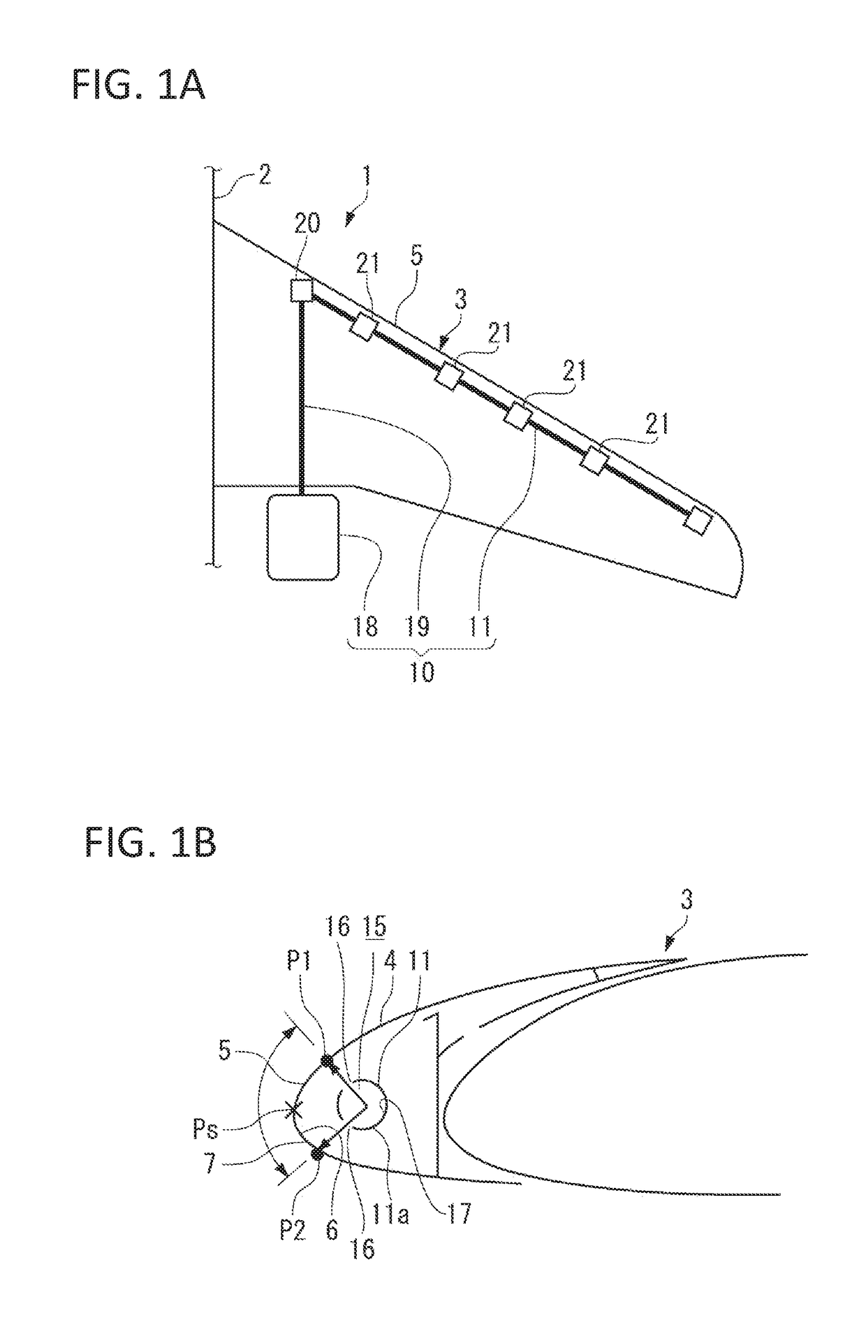
[0035]As illustrated in FIGS. 1A and 1B, an anti-icing system 10 according to the present embodiment is provided inside a slat 3 of a main wing 1 of an aircraft, and prevents icing on an outer surface 7 of a leading edge 5 of the slat 3 of the main wing 1.

[0036]The slat 3 has an outer hull configured of a wing panel 4. The wing panel 4 may be made of, for example, an aluminum alloy, or a fiver reinforced resin such as carbon fiber reinforced plastics (CFRP) and glass fiver reinforced plastics (GFRP). As illustrated in FIG. 1B, a cross-sectional surface of the leading edge 5 along a wing length direction of the wing panel 4 has a curved shape derived from bending process. The anti-icing system 10 ejects, as high-temperature high-speed jet flow, bleed air that is heated gas, toward an inner surface 6 of the leading edge 5, thereby preventing icing on the outer surface 7.

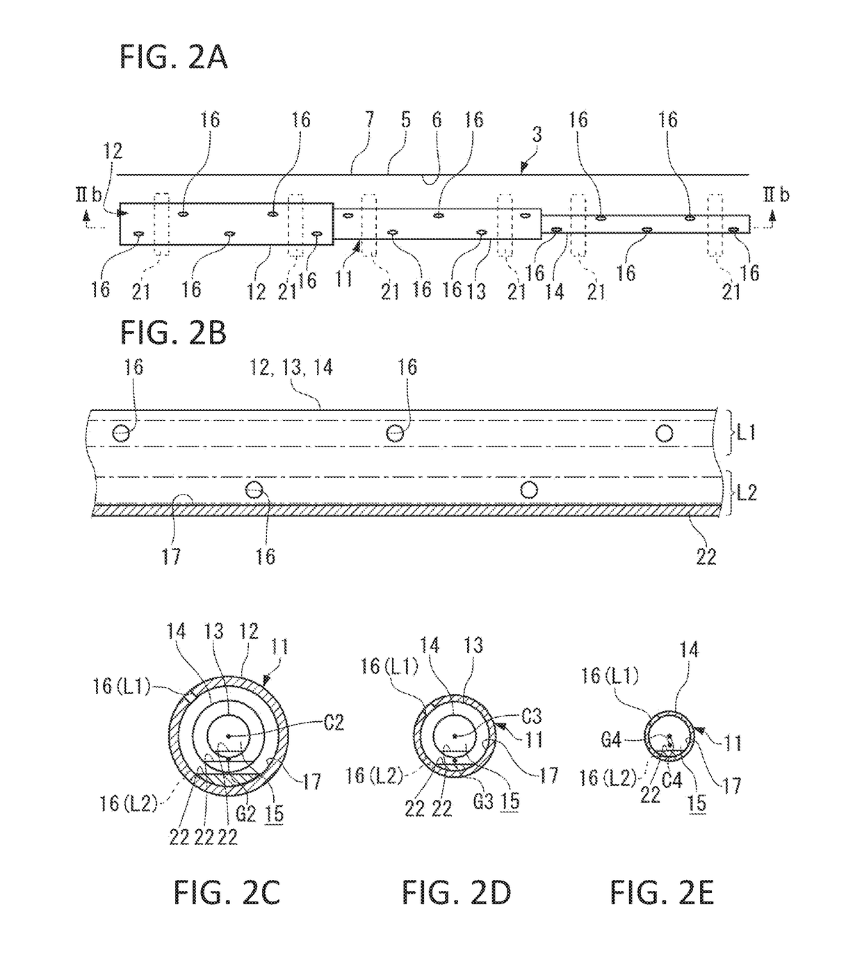
[0037]As illustrated in FIGS. 1A and 1B, the anti-icing system 10 includes, in order to eject the bleed air toward t...

second embodiment

[0065]Next, a second embodiment of the present invention is described. Note that components of the second embodiment similar to those of the first embodiment are denoted by the reference numerals same as those in the first embodiment, and description of such components are omitted.

[0066]Unlike the first embodiment, the piccolo tube 11 used in the second embodiment has a centroid coincident with the center, and is unrotatably disposed inside the main wing 1. As illustrated in FIGS. 6A and 6B, a partition 24 is provided inside the piccolo tube 11 along a central axis of the piccolo tube 11 through welding or other process. The partition 24 equally partitions the flow path 15 into an upper flow path 15a corresponding to the first ejection hole line L1 and a lower flow path 15b corresponding to the second ejection hole line L2.

[0067]The piccolo tube 11 includes a first damper 25 at an end from which the bleed air flows in. The first damper 25 adjusts a flowing amount of the bleed air to...


PUM


Abstract

There is provided an anti-icing system that has a simple structure and makes it possible to exert anti-icing performance by dealing with displacement of a stagnation point without increasing air resistance. The anti-icing system according to the present invention blows heated gas to an inner surface of a wing of an aircraft, and includes: a piccolo tube that includes a flow path through which the heated gas flows in a longitudinal direction from a rear end to a front end, and a plurality of ejection holes provided along the longitudinal direction to make the flow path communicate with an outside; and a supply source that supplies the heated gas toward the piccolo tube. The piccolo tube is held to cause positions of the respective ejection holes to be fixed in a gravity direction.

Description

BACKGROUND OF THE INVENTION[0001]Field of the Invention[0002]The present invention relates to an anti-icing system that prevents icing on a leading edge of an aircraft, and to an aircraft including the anti-icing system.[0003]Description of the Related Art[0004]During flight of an aircraft, icing occurs on an outer surface of a leading edge in a traveling direction of the aircraft, such as a main wing, a tail wing, and an air intake, due to collision of supercooled droplets in the air. The icing phenomenon variously influences flight of the aircraft. Therefore, an anti-icing system that prevents icing by various heating means are provided at positions that may be particularly affected by the icing phenomenon.[0005]In an aircraft including a turbine engine, as one of the anti-icing system, bleed air that is high-temperature high-pressure air extracted from an engine compressor has been widely used as a heating source. In such an anti-icing system, the bleed air is guided through a pi...

Claims


Application Information

Patent Timeline
IPC IPC(8): B64D15/04
CPCB64D15/04
Inventor ISHIDA, TOSHIYUKIICHIKAWA, GENTOUEFUJI, YOICHIMORISHITA, MASATOSHIKAWAI, KAZUHIROWATANABE, SATOSHIFUJITA, GO
Owner MITSUBISHI AIRCRAFT
Why Eureka
Try Eureka