Model based testing of rotating borehole components

US20170218733A1Inactive Publication Date: 2017-08-03BAKER HUGHES INC

Image

  • Model based testing of rotating borehole components
  • Model based testing of rotating borehole components
  • Model based testing of rotating borehole components

Examples


embodiment 1

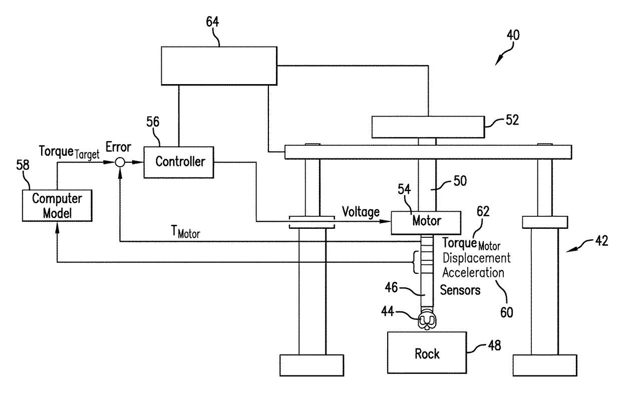
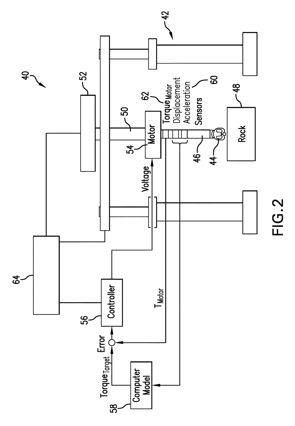
[0098]A method of testing a downhole component, comprising: selecting a downhole component to be tested, the downhole component configured to be incorporated in a drilling assembly that includes a connecting string configured to connect the downhole component to a surface location; generating a mathematical drilling assembly model, the drilling assembly model representing the connecting string as a virtual connecting string and describing a behavior of the connecting string in response to rotation of the drilling assembly by a virtual top drive; disposing the downhole component, by a support structure, at a sample of a formation material, and rotating the downhole component by applying a torque to the downhole component via a torque motor based on the drilling assembly model and a selected rotational rate of the virtual top drive; during the rotating, receiving real time measurements of an angular velocity of the downhole component; inputting the angular velocity into the drilling a...

embodiment 2

[0099]The method of embodiment 1, wherein the torque motor is configured to apply the applied torque to the downhole component in the absence of a physical structure corresponding to the connecting string.

embodiment 3

[0100]The method of embodiment 1, wherein the drilling assembly model describes interactions between the virtual connecting string and a borehole during rotation of the virtual connecting string.


PUM


Abstract

A method of testing a downhole component configured to be incorporated in a drilling assembly includes generating a mathematical drilling assembly model representing a connecting string as a virtual connecting string and describing a behavior of the connecting string in response to rotation of the drilling assembly, disposing the downhole component at a sample of a formation material, and rotating the downhole component by applying a torque to the downhole component via a torque motor based on the drilling assembly model and a selected rotational rate of a virtual top drive. The method further includes inputting real time measurements of an angular velocity of the downhole component into the drilling assembly model, calculating a target torque corresponding to an amount of torque that would be applied to the downhole component by the virtual connecting string, and adjusting the applied torque from the torque motor to correspond to the target torque.

Description

BACKGROUND[0001]Various operations are performed by the energy industry to evaluate earth formations and produce hydrocarbons. Such operations include drilling, stimulation and production. During a drilling operation, a drill string is deployed in an earth formation, which typically includes components such as a drill bit and bottomhole assembly (BHA) components. The proper design of the drill bit and other BHA components is important to ensure efficient and effective drilling and maximize the life of the components. In addition, proper design is important to mitigate deleterious effects including torsional vibrations such as stick-slip and tool face oscillation.[0002]The main cause of torsional vibrations is the relatively thin drill string and the extremely high ratio between length and diameter. Knowledge of the nature of torsional vibrations, and how to prevent their genesis or suppress them, is an important aspect of downhole component design. To facilitate the design of drill ...

Claims


Application Information

Patent Timeline
03 Aug 2017
Publication
US20170218733A1
IPC
E21B43/00; G06F17/11; E21B44/02
CPC
E21B43/00; G06F17/11; E21B44/02; E21B44/00; E21B10/00; G06F30/20
Inventors
JAIN, JAYESH J.; ICHAOUI, MOHAMED