

Lubricating Device of Power Transmission Device for Vehicle
- Summary
- Abstract
- Description
- Claims
- Application Information
AI Technical Summary
Benefits of technology
Problems solved by technology
Method used
Image

Examples
first embodiment
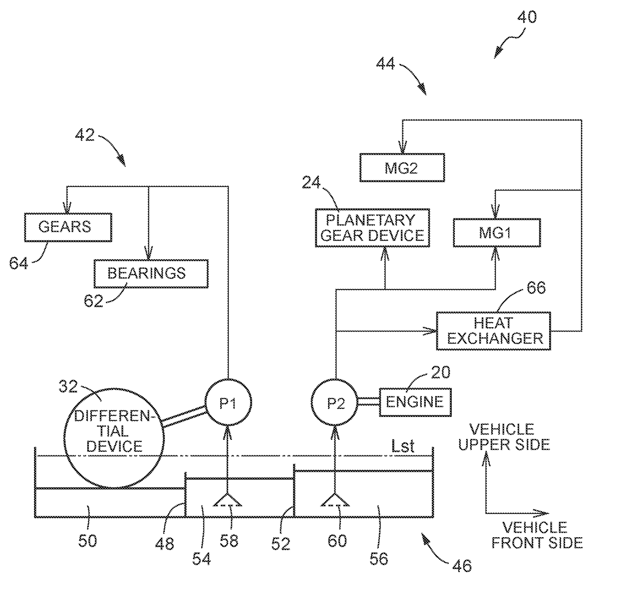
[0046]On the other hand, during the operation of the first oil pump P1 or the second oil pump P2, including during the travel of the vehicle, the oil level is lowered due to the scraping-up of the lubricating oil by the differential ring gear Gd and so on and due to the suction of the lubricating oil by the first oil pump P1 or the second oil pump P2, that rotate according to a vehicle speed V, and becomes lower than the partition wall 48, 52. In the first oil storage portion 50, the oil level is determined by the balance between the scraping-up by the differential ring gear Gd and so on and the return oil amount. In the second oil storage portion 54, the oil level is determined by the balance between the suction of the lubricating oil by the first oil pump P1 and the return oil amount. In the third oil storage portion 56, the oil level is determined by the balance between the suction of the lubricating oil by the second oil pump P2 and the return oil amount. In the first embodiment...
second embodiment
[0063]First, the present disclosure will be described. A lubricating device 100 of FIG. 6 is configured such that a first oil pump P1 is coupled to a differential device 32 via a pump connecting / disconnecting device 102 that connects / disconnects power transmission, and is coupled to another rotary drive source 104 so as to be rotationally driven. The pump connecting / disconnecting device 102 is a clutch, a one-way clutch, or the like and is disposed between the first oil pump P1 and a pump drive gear Gp. While a pump-driving electric motor, for example, is preferably used as the other rotary drive source 104, the first oil pump P1 may alternatively be rotationally driven mechanically by the engine 20. In this case, the first oil pump P1 may be coupled to the engine 20 via a second pump connecting / disconnecting device such as a clutch or a one-way clutch. In this case, the first oil pump P1 can be driven at a rotational speed not depending on a vehicle speed V, including during the st...
fourth embodiment
[0066]Next, the present disclosure will be described. A lubricating device 210 of FIG. 8 is configured such that the second oil pump P2 is omitted in the lubricating device 200 described above, that a second supply route 44 is connected to a first supply route 42, and that lubricating oil is supplied also to the second supply route 44 from a first oil pump P1.
PUM
 Abstract
Description
Claims
Application Information