Unpowered non-force self-flat-pressing oil groove integrated flotation seal device

A floating seal, oil pressure tank technology, applied in the direction of hydropower, engine components, machines/engines, etc., can solve the problems of high labor intensity, long construction period, large workload, etc., and achieve simple and convenient dismantling and installation, long replacement time, The effect of short replacement time

Pending Publication Date: 2020-07-10
HARBIN XUNPU TECH DEV
View PDF0 Cites 1 Cited by
  • Summary
  • Abstract
  • Description
  • Claims
  • Application Information

AI Technical Summary

Problems solved by technology

[0002] At present, the thrust of the hydro-generator unit and the turbine oil in the oil grooves of each guide bearing overflow outward at the position of the dynamic and static seal gaps. First, the volume of the thrust bearing oil tank is large, and there is a lot of turbine oil. The diameter of the rotating mirror tile is large, and its linear speed is high. The impact on the turbine oil causes serious expansion of the turbine oil. The high temperature generated by the friction of the mirror plate makes the turbine oil produce a certain amount of oil fume, and the expanded oil mist and oil fume generated by friction generate a certain pressure in the oil tank. Under the internal pressure of the oil tank, the oil mist overflows outward; second, the thrust The split seat ring above the bearing oil groove is at the center of the generator cooling air. The cooling air used to cool the stator coil and the rotor coil generates an annular negative pressure area on the surface of the large shaft and the upper ring surface. This annular negative pressure area It produces external suction to the puffed oil mist in the oil tank, which intensifies the phenomenon of oil mist and oil fume overflowing from the oil tank; thirdly, the current split floating sealing body adopts a decentralized assembly method, which not only has extremely poor sealing performance, but also has other problems
The oil mist spilling out will harm the insulation life of the stator and rotor coils of the generator, and pollute the downstream people's water and ecological environment
In order to solve this problem in the prior art, a powered oil-absorbing mist purifier is used to purify and decompress the oil mist and oil fume in the oil tank, so as to prevent the oil mist and oil fume from entering the dynamic and static seal between the split floating seal body and the surface of the large shaft. Outward overflow, because the fan of the oil suction mist purifier forcibly absorbs oil mist and oil fume from the oil tank, it intensifies the generation of more puffed oil mist in the turbine oil, and rapidly reduces the safe oil level of the turbine oil for lubrication and cooling. As a result, the temperature of the mirror tiles rises and increases the workload of the oil-absorbing mist purifier, resulting in a reduction in the purification rate and even invalidation of the oil-absorbing mist purifier.
In the existing technology, in order to overcome the annular negative pressure area generated by the cooling wind on the thrust oil groove seat, the ring cavity is vacuumed, and the inside of the ring cavity is forced to be filled with air, and the charged air is discharged outward through the dynamic and static gap of the upper ring surface to form a high-speed jet. effect, this existing scheme of forced air filling not only failed to eliminate the vacuum problem of the annular cavity, but the jet effect produced further exacerbated the overflow of oil mist and oil fume in the oil tank. After the application of these existing technologies in several power stations, it proved that the technology The effect is unsatisfactory, it does not meet the technical requirements, and there are places that violate science and technology
The defect of the existing technology in the processing and installation of the split floating sealing body is that the rectangular groove ring is directly processed on the inner diameter (large shaft side) of the upper ring surface and the lower ring surface of the split seat ring, which will have a spring and a positioning ring. Hundreds of split floating sealing bodies in the waist hole are installed in the double-layer rectangular groove ring one by one
The split floating seal is a wearing part that often needs to be replaced. It is very difficult to replace the split floating seal in the prior art. In a very small generator room, dozens of worn split floating seals need to be changed from hundreds of pieces per flap. It is necessary to remove dozens of new split-lobe floating seals in the rectangular groove ring of the split-lobe seat ring, and the upper and lower layers of each petal seat ring, each Each layer must be equipped with 4 to 16 pieces of split floating seals, and a whole split seat ring is composed of 4 to 12 petals, so replacing a split floating seal is not only heavy workload, high labor intensity, long construction period, but also often Causes damage to the floating sealing body of the split valve, resulting in extremely poor sealing

Method used


Image

  • Unpowered non-force self-flat-pressing oil groove integrated flotation seal device
  • Unpowered non-force self-flat-pressing oil groove integrated flotation seal device
  • Unpowered non-force self-flat-pressing oil groove integrated flotation seal device

Examples


Embodiment Construction

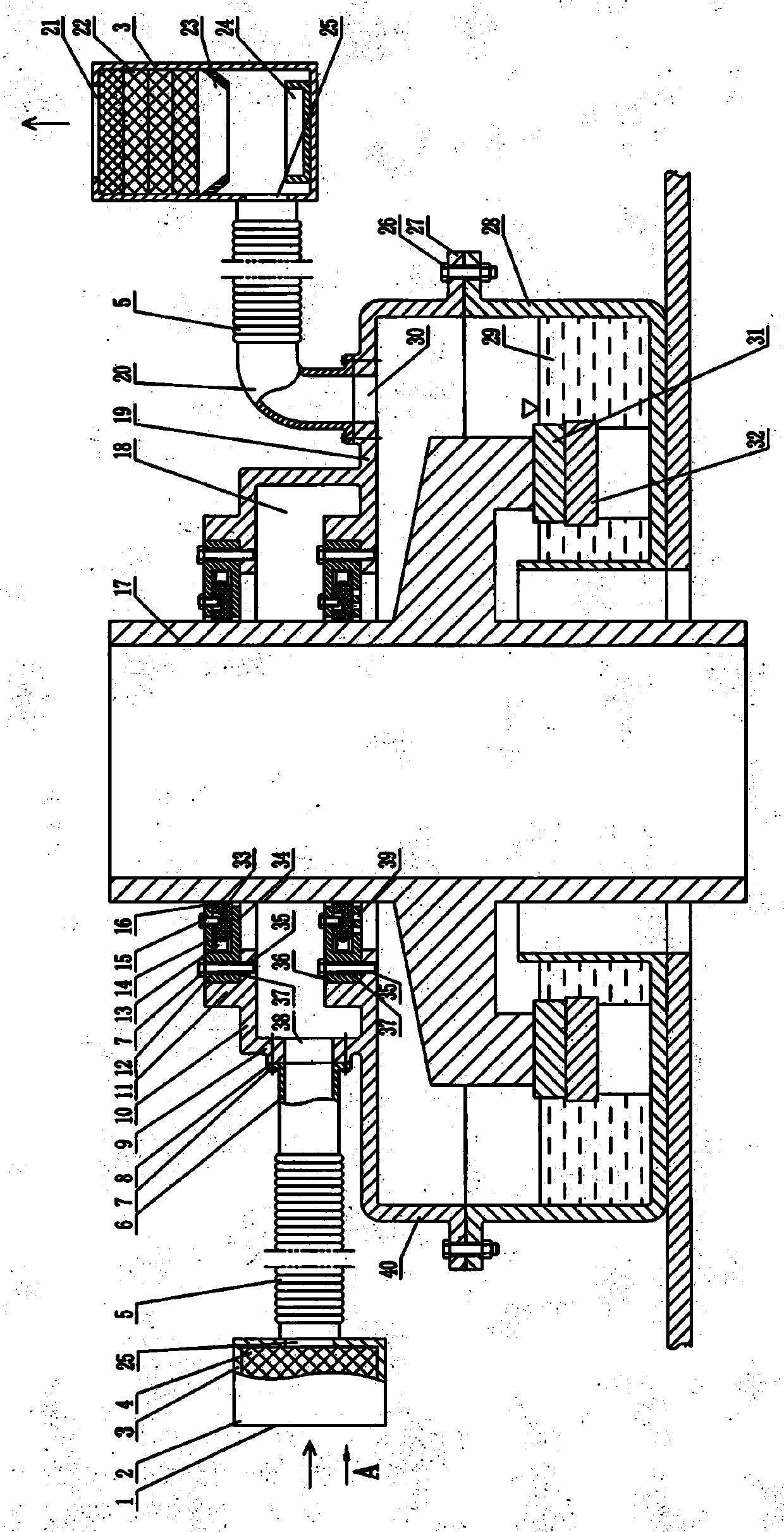
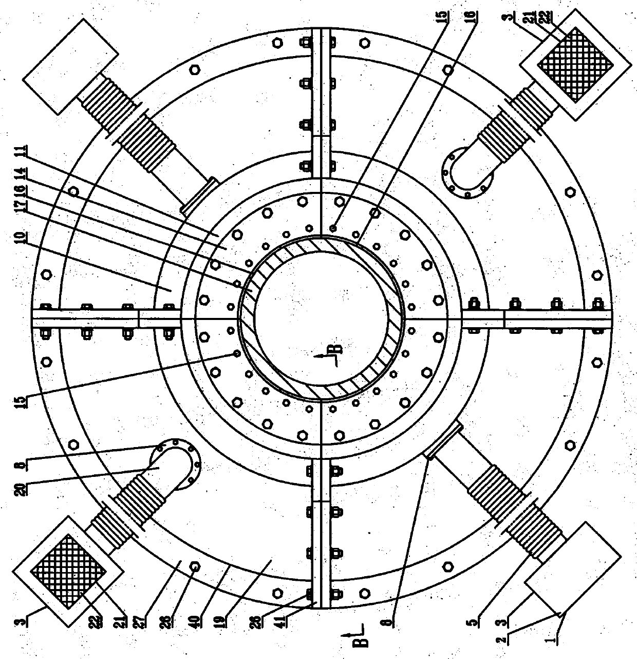
[0025]A stop ring 11 is processed on the inner diameter side of the upper ring surface 10 and the lower ring surface 19 of the split seat ring 40 with the seat ring flange 27 and the joint surface 41, and the air inlet hole is processed on the vertical ring surface 9. 38, on the lower ring surface 19 of the outer side of the vertical ring surface 9, a flat pressure through hole 30 is processed, and the upper integrated rectangular groove ring 12 is formed by the upper ring 14 of the moment groove, the lower ring 34 of the moment groove and the fixing hole 37. Groove upper ring 14, the moment groove lower ring 34 with a plurality of oil injection holes 39 and the fixing hole 37 have formed the lower integrated rectangular groove ring 36, and each group has 4~16 pieces of backs that are fixed with pretension springs 13, with The split floating sealing body 16 of the positioning waist hole 33 is respectively placed in the upper integrated rectangular groove 12 and the lower integr...


PUM


Abstract

The invention discloses an unpowered non-force self-flat-pressing oil groove integrated flotation seal device. Baffle rings are mounted on the upper ring face and the lower ring face of a sectioning seat ring with a seat ring flange and an occlusal face, upper integrated rectangular groove rings internally provided with 4 to 16 sectioning floating seal bodies are fixed to a baffle ring inner sideupper ring face, the 4 to 16 sectioning floating seal bodies are mounted inside, lower integrated rectangular groove rings with rectangular groove lower rings provided with oil filling holes are fixedto a baffle ring inner side lower ring face, an air inlet hole in a vertical ring face communicates with an air filter with a flat pressing hole and an air opening and internally provided with an airfilter body through a connecting pipe and a connecting hose, a flat pressing through hole in the lower ring face communicates with a shell with a flat pressing hole, provided with a flat pressing opening in the upper portion, and internally provided with a multi-layer oil mist filter body, a flow guide frame and an oil collection box through a flat pressing pipe and a connecting hose, the sectioning seat ring forms a whole circle through the occlusal face via occlusal bolts, through the seat ring flange, the occlusal bolts are used for fixing the whole sectioning seat ring to an oil groove, and the device can be widely applied to the field of hydro-generators and the like.

Description

Technical field: [0001] The invention relates to a device for sealing the dynamic and static positions of the thrust bearing and the guide bearing oil groove of a water turbine generator set. Background technique: [0002] At present, the thrust of the hydro-generator unit and the turbine oil in the oil grooves of each guide bearing overflow outward at the position of the dynamic and static seal gaps. First, the volume of the thrust bearing oil tank is large, and there is a lot of turbine oil. The diameter of the rotating mirror tile is large, and its linear speed is high. The impact on the turbine oil causes serious expansion of the turbine oil. The high temperature generated by the friction of the mirror plate makes the turbine oil produce a certain amount of oil fume, and the expanded oil mist and oil fume generated by friction generate a certain pressure in the oil tank. Under the internal pressure of the oil tank, the oil mist overflows outward; second, the thrust The ...

Claims


Application Information

Patent Timeline
Patent Type & Authority Applications(China)
IPC IPC(8): F03B11/00F01D25/18F01D11/00
CPCF01D11/003F01D25/18F01D25/183F03B11/00F03B11/006Y02E10/20
Inventor 韩宏波
Owner HARBIN XUNPU TECH DEV
Why Eureka
Try Eureka