Connector for matrix connection between a housing and a support, comprising a bent main body

a technology of connecting rods and supporting rods, which is applied in the direction of coupling device connections, contact member manufacturing, electrical apparatus, etc., can solve the problems of degrading the mechanical and/or electrical functions of the package, unable to withstand the great side differential movement between the package and the microelectronic support, and unable to connect through the periphery of the package, etc., to achieve simple and robust design, moderate cost, and easy calculation

Active Publication Date: 2017-08-03
COMMISSARIAT A LENERGIE ATOMIQUE ET AUX ENERGIES ALTERNATIVES
View PDF3 Cites 0 Cited by
  • Summary
  • Abstract
  • Description
  • Claims
  • Application Information

AI Technical Summary

Benefits of technology

[0020]Consequently, there is a need for providing an alternative solution of a connector being advantageously flexible between a package and a support, in particular a printed circuit, such a connector being in particular of a simple des

Problems solved by technology

Hence, the connection through the periphery of the package becomes difficult, or even impossible, and it is generally preferred a connection through a grid array (possibly incomplete), that is an array or a grid, of connectors placed on most of one of the faces of the package.
However, the drawback with using such metal balls is generally that they are not able to withstand great side differential movements between the package and the microelectronic support, without degrading their mechanical and/or electrical functions.
However, the drawbacks of these metal columns are that they have a high manufacturing cost and they are complicated to produce, in particular in case of the presence of an inner or outer structure, or to be installed to the package.
Moreover,

Method used


Image

  • Connector for matrix connection between a housing and a support, comprising a bent main body
  • Connector for matrix connection between a housing and a support, comprising a bent main body
  • Connector for matrix connection between a housing and a support, comprising a bent main body

Examples


Embodiment Construction

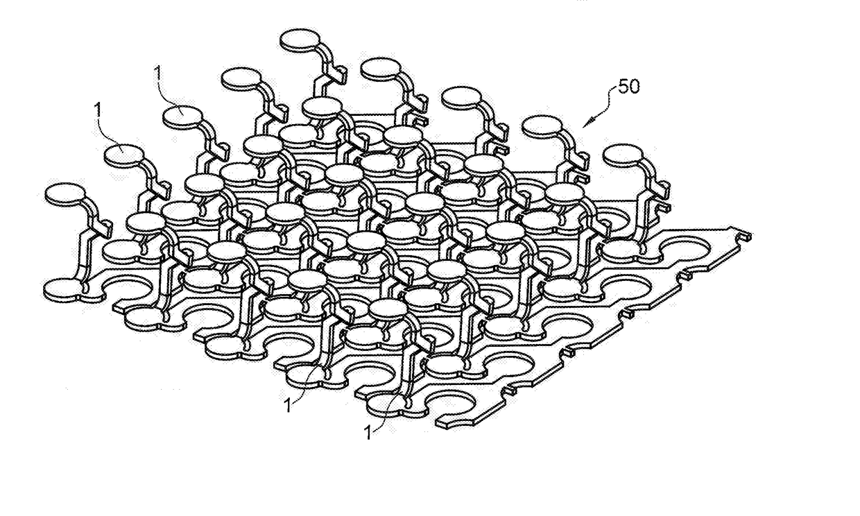
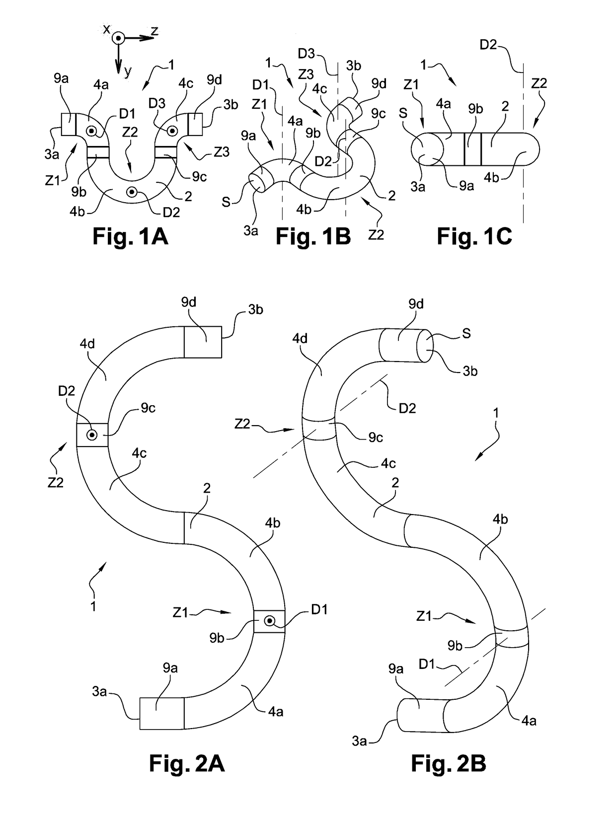
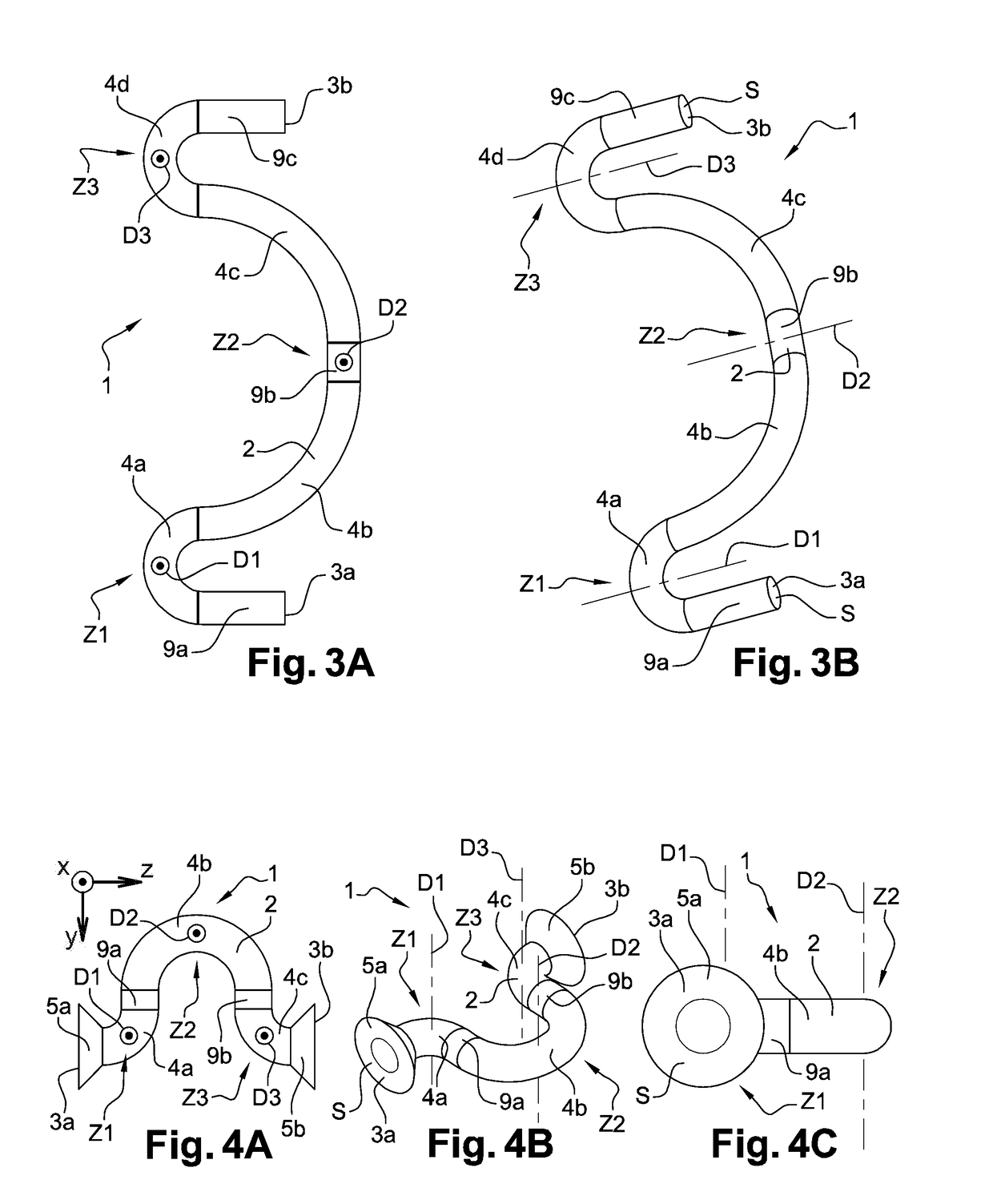
[0077]In reference to FIG. 1A to 8C, eight exemplary embodiments of connectors 1 in accordance with the invention have, been represented. Such connectors 1 are in particular intended to allow a microelectronic package and a microelectronic support, and in particular a printed circuit to be connected as a grid array.

[0078]According to a first alternative in reference to FIG. 1A to 4C, the connectors 1 can be in the form of folded metal wires.

[0079]According to a second alternative in reference to FIG. 5A to 7C, the connectors 1 can be in the form of folded metal strips.

[0080]Finally, according to a third alternative in reference to FIG. 8A to 8C, the connector 1 can be in the form of a plate, and in particular in the form of a folded metal sheet.

[0081]In all these exemplary embodiments of connectors 1 in accordance with the invention in reference to FIG. 1A to 8C, each connector 1 includes a main body 2 provided with a first end 3a for being connected with the microelectronic package...


PUM


Abstract

An electrical connector allowing a connection between two substantially facing electrical contacts respectively pertaining to a housing and a support, and including a main body including a first end for secure connection thereof to the housing and a second end for secure connection thereof to the support, the main body being bent in at least one bending area.

Description

TECHNICAL FIELD[0001]The present invention relates to the general field of connector technology, in particular for microelectronics, and more specifically to the field of mechanical and electrical connection means between a package, which is in particular microelectronic can be of a relatively great dimension, and a support, which is in particular microelectronic and can be for example a printed circuit board. Specifically, the invention is concerned with such connection means provided to withstand mechanical deformations without degrading their functions.[0002]The invention finds for example favoured applications in the fields of computer science, telephony, avionics, spatial electronics and automotive electronics, so-called airborne electronics, as well as for most of nomadic electronic objects, among other things.[0003]It thus provides a connector for a grid array connection between a package and a support, a device including a plurality of such connectors arranged as a grid arra...

Claims


Application Information

Patent Timeline
IPC IPC(8): H01R12/52H01R13/24H01R43/16H01L23/00
CPCH01R12/52H01L24/67H01L2224/67H01R43/16H01R13/2435
Inventor DE CRECY, FRANCOISDIEM, BERNARDFERRANDON, CHRISTINEHILT, THIERRY
Owner COMMISSARIAT A LENERGIE ATOMIQUE ET AUX ENERGIES ALTERNATIVES
Why Eureka
Try Eureka