External rotor motor and air conditioner comprising the same

a technology of external rotor motor and air conditioner, which is applied in the direction of magnetic circuit rotating parts, ventilation systems, magnetic circuit shape/form/construction, etc., can solve the problems of air conditioners, external rotor motors that are bulky, air conditioners that are not balanced, etc., and achieve high measuring accuracy, quick temperature sense, and high degree of automation

Active Publication Date: 2017-08-03
ZHONGSHAN BROAD OCEAN
View PDF10 Cites 8 Cited by
  • Summary
  • Abstract
  • Description
  • Claims
  • Application Information

AI Technical Summary

Benefits of technology

[0034]6. The fixing frame comprises an annular portion and a clamping portion. The clamping portion bulges outwards from the annular portion. A cylindrical body is disposed in a center of the terminal insulator. The annular portion is sleeved on the cylindrical body, and the clamping portion is disposed on the coil windings. The thermostat is disposed on the clamping portion and is in the vicinity of the coil windings. The arrangement is simple. The thermostat is reliable and can quickly sense the temperature.
[0035]7. The clamping portion is provided with mounting slots. The thermostat is mounted in the mounting slot. A bottom of the mounting slot is a through hole, and the thermostat is in the vicinity of the coil windings. The thermostat which features higher measuring accuracy can quickly sense the temperature and protect the plastic-packaged stator. The clamping portion is provided with a fixing block. The fixing block is configured to fix the thermostat in the mounting slot. The arrangement is simple, and the assembly is reliable. Two sides of the clamping portion are provided with slots, and a top surface of the terminal insulator is provided with cylinders. The cylinders are secured to the slots. The arrangement is simple, and the positioning and the assembly are convenient.
[0036]8. One end of the outer side of the sleeve base in the vicinity of the plastic-packaged end plate is provided with a plurality of second reinforcing ribs in the radial direction. The plastic-packaged body is sleeved on the second reinforcing ribs, therefore, the bonding strength between the sleeve base and the plastic-packaged body is enhanced, and the risk of the plastic-packaged body detaching from the sleeve base is lowered; the reliability of the plastic-packaged stator is improved, and the service life of the plastic-packaged stator is prolonged. In addition, the second reinforcing ribs can be used for heat dissipation. The heat generated by the bearing during the high-speed operation can be dissipated via the second reinforcing ribs and the plastic-packaged body, so as to avoid adverse effect of high temperature on the bearing.
[0037]9. Two adjacent second reinforcing ribs form a pair of second reinforcing ribs, and the pair of second reinforcing ribs is V-shaped. A connecting member is disposed between the two adjacent second reinforcing ribs and on one end of the sleeve base. The connecting member is configured to connect the two adjacent second reinforcing ribs. The second reinforcing ribs protrudes out from an outer side surface of the stator core along the radial direction. The arrangement is simple, and the bonding strength between the sleeve base and the plastic-packaged body is enhanced, thus the risks of the plastic-packaged body detaching from the sleeve base is lowered, and the reliability of the plastic-packaged stator is improved.
[0038]10. The sleeve base is metal material. The sleeve base is disposed in the axle hole and matches with an inner wall of the axle hole. The arrangement is simple, and the assembly of the sleeve base is convenient, accurate, and reliable. The coaxiality of the bearing is effectively enhanced, and the vibration and noises produced during the operation of the motor are reduced. The bearing is disposed in the sleeve base, and at least part of the bearing is inserted in the axle hole in a center of the stator core. The heat generated by the bearing during operation can be dissipated via the sleeve base and the stator core, and the heat dissipation potential of the bearing is enhanced, thus the heat dissipation problem of the bearing in the external rotor motor is effectively solved. The motor is reliable, and the service life thereof is prolonged.
[0039]11. The external rotor motor is mounted in the outdoor unit of the air conditioner via the mounting portion on the outer edge of the plastic-packaged end plate. The arrangement is simple. The mounting position is only one in number, thus the buffer ring and the mounting support are reduced, and the production cost is saved.

Problems solved by technology

The external rotor and the fan blades are arranged on the same side of the plastic-packaged stator, leading to the following problems:1) the external rotor motor is not balanced and is unstable during rotation;2) air conditioners that include the external rotor motor are bulky; and3) a significant amount of noise is produced during the operation of the external rotor motor.

Method used


Image

  • External rotor motor and air conditioner comprising the same
  • External rotor motor and air conditioner comprising the same
  • External rotor motor and air conditioner comprising the same

Examples


example 1

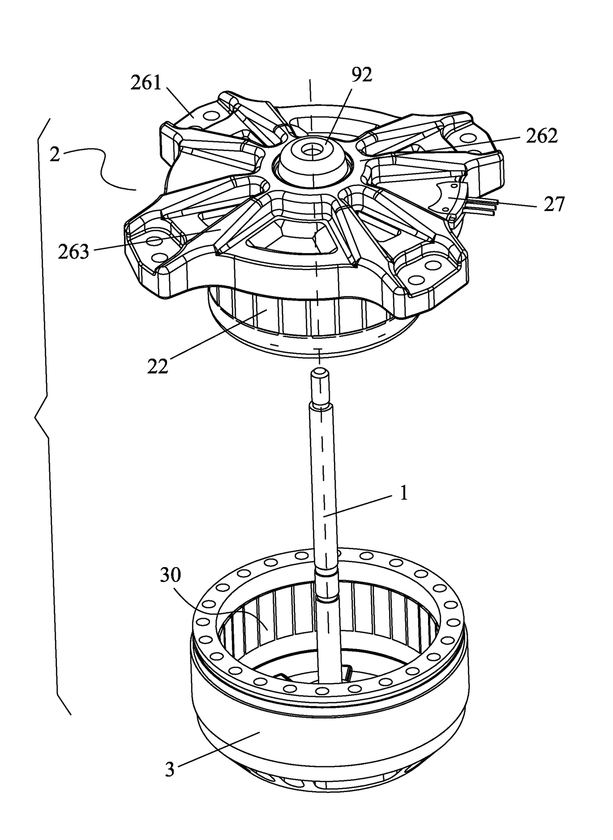
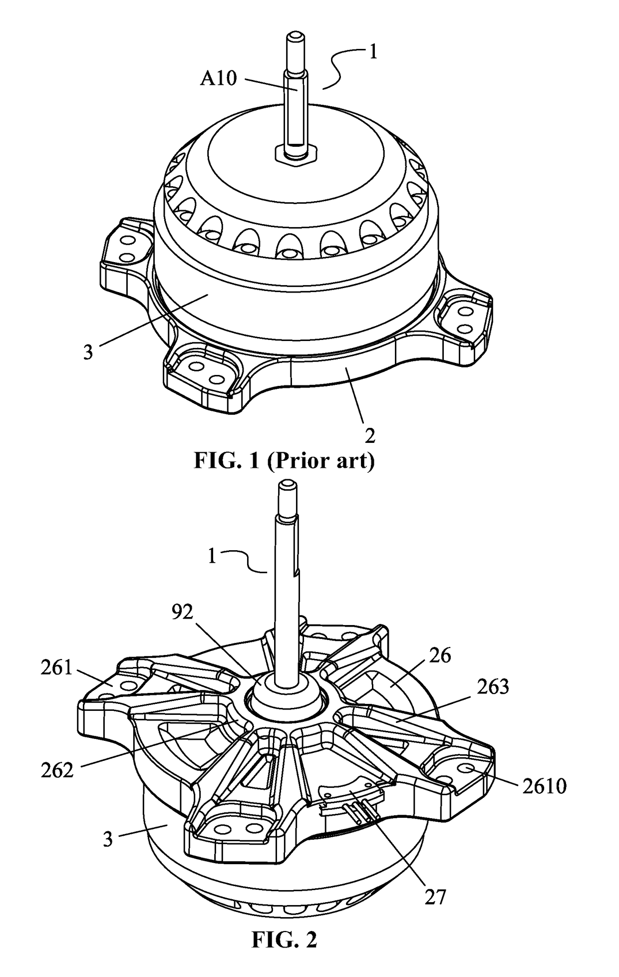
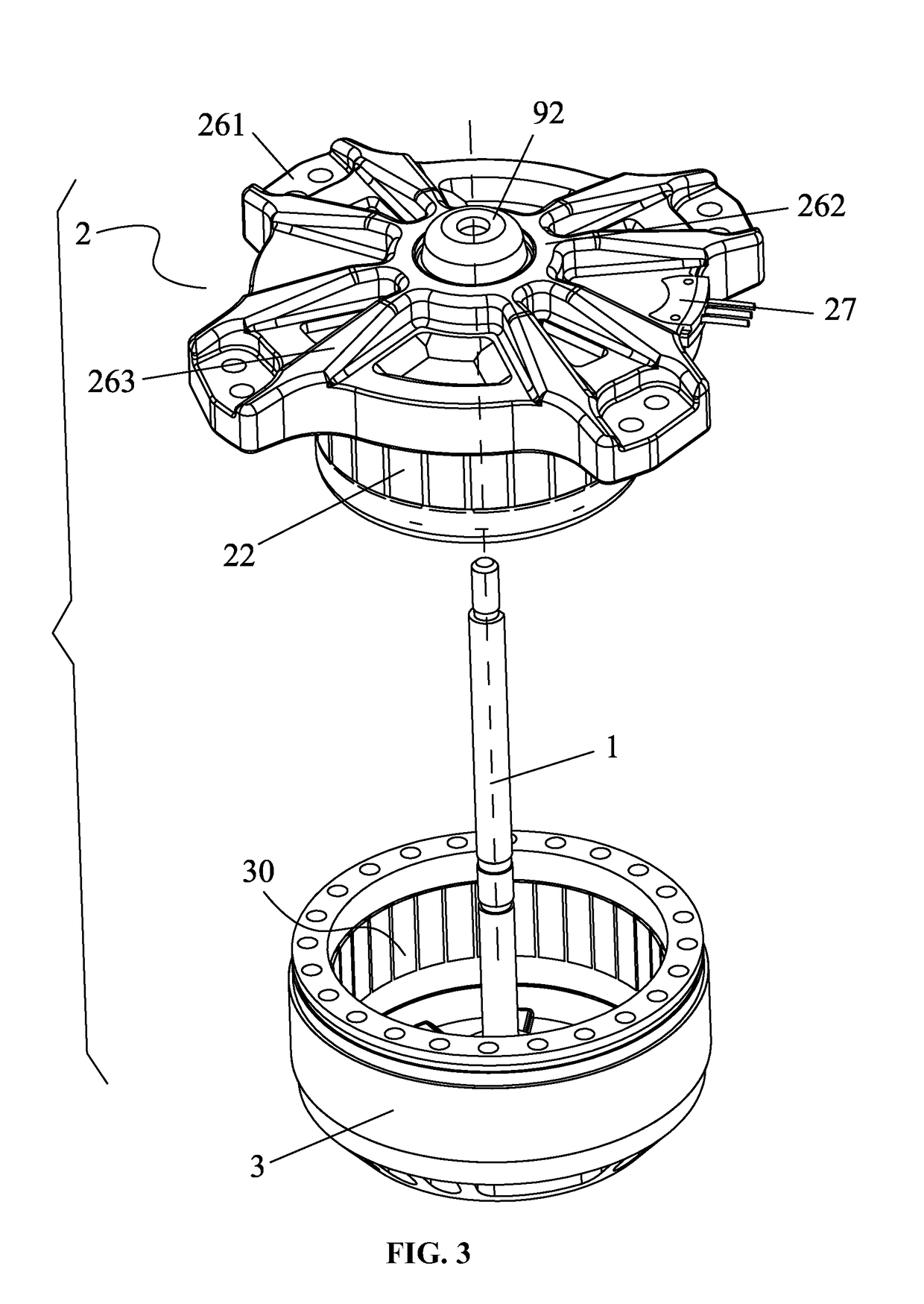
[0080]As shown in FIGS. 2-5, an external rotor motor comprises a rotary shaft 1, a plastic-packaged stator 2, and an external rotor 3. The plastic-packaged stator 2 is disposed in a chamber 30 of the external rotor 3. The plastic-packaged stator 2 comprises a sleeve base 21, a stator core 22, a terminal insulator 23, coil windings 24, and a plastic-packaged body 25. The terminal insulator 23 is disposed on an end surface of the stator core 22. The coil windings 24 are coiled on the terminal insulator 23. The sleeve base 21 is disposed in an axle hole 220 of the stator core 22. The plastic-packaged body 25 integrates the sleeve base 21, the stator core 22, the terminal insulator 23, and the coil windings 24. A plastic-packaged end plate 26 is disposed on the plastic-packaged body 25 on one side of the stator core 22. Bearing housings are disposed on two ends of the sleeve base 21. Each bearing housing comprises bearings 4. The rotary shaft 1 is disposed in the sleeve base 21, and two...

example 2

[0082]As shown in FIG. 6, the stator core 22 comprises a plurality of laminated punching sheets 5. The laminated punching sheets 5 each comprise a circular yoke 50, and a plurality of first tooth portions 51 and second tooth portions 52 on an outer edge of the circular yoke 50. The first tooth portions 51 and the second tooth portions 52 are circumferentially arranged at intervals. The second tooth portions 52 each comprise a tooth root 521, a first curved tooth 522, a straight tooth 523, and a second curved tooth 524. The first curved tooth, the straight tooth, and the second curved tooth extend out from the tooth root 521. The straight tooth 523 is configured to separate the first curved tooth 522 from the second curved tooth 524, and first winding slots 501 are formed therebetween. Two second winding slots 502 are formed between the tooth root 521, the first curved tooth 522, the second curved tooth 524 of the second tooth portions 52 and the adjacent first tooth portion 51. A de...

example 3

[0085]As shown in FIGS. 8-11, the plastic-packaged stator 2 further comprises a thermostat 6 and a fixing frame 7. The fixing frame 7 comprises an annular portion 71 and a clamping portion 72. The clamping portion bulges outwards from the annular portion 71. A cylindrical body 231 is disposed in a middle of the terminal insulator 23. The annular portion 71 is sleeved on the cylindrical body 231, and the clamping portion 72 is disposed on the coil windings 24. The thermostat 6 is disposed on the clamping portion 72 and is in the vicinity of the coil windings 24. The clamping portion 72 is provided with mounting slots 720. The thermostat 6 is mounted in the mounting slot 720. A bottom of the mounting slot 720 is a through hole 7200, and the thermostat 6 is in the vicinity of the coil windings 24. The clamping portion 72 is provided with a fixing block 721. The fixing block 721 is configured to fix the thermostat 6 in the mounting slot 720. Two sides of the clamping portion 72 are prov...


PUM


Abstract

An external rotor motor, including a rotary shaft, a plastic-packaged stator, and an external rotor. The plastic-packaged stator includes a sleeve base, a stator core, a terminal insulator, coil windings, and a plastic-packaged body. The plastic-packaged stator is disposed in the chamber of the external rotor. The terminal insulator is disposed on the end surface of the stator core. The coil windings are coiled on the terminal insulator. The sleeve base is disposed in an axle hole of the stator core. The plastic-packaged body integrates the sleeve base, the stator core, the terminal insulator, and the coil windings. A plastic-packaged end plate is disposed on the plastic-packaged body on one side of the stator core. Bearing housings are disposed on two ends of the sleeve base. The rotary shaft is disposed in the sleeve base, and two ends of the rotary shaft are supported by bearings.

Description

CROSS-REFERENCE TO RELATED APPLICATIONS[0001]This application is a continuation-in-part of International Patent Application No. PCT / CN2015 / 090610 with an international filing date of Sep. 24, 2015, designating the United States, now pending, and further claims foreign priority benefits to Chinese Patent Application No. 201520043550.1 filed Jan. 21, 2015, Chinese Patent Application No. 201520043548.4 filed Jan. 21, 2015, Chinese Patent Application No. 201520043515.X filed Jan. 21, 2015, Chinese Patent Application No. 201520213499.4 filed Apr. 10, 2015, Chinese Patent Application No. 201520435422.1 filed Jun. 23, 2015, Chinese Patent Application No. 201520435300.2 filed Jun. 23, 2015, and Chinese Patent Application No. 201520435462.6 filed Jun. 23, 2015. The contents of all of the aforementioned applications, including any intervening amendments thereto, are incorporated herein by reference. Inquiries from the public to applicants or assignees concerning this document or the related a...

Claims


Application Information

Patent Timeline
Patent Type & Authority Applications(United States)
IPC IPC(8): H02K1/22F24F7/007F24F1/22H02K7/14H02K7/08
CPCH02K1/22H02K7/14F24F7/007F24F1/22H02K7/08F24F1/38H02K21/22H02K1/146H02K1/187H02K5/1735H02K2213/03H02K11/25H02K1/2791H02K5/16H02K5/173H02K5/1732
Inventor WANG, XIONGCHENGFU, GUIWENZHU, JINCHENGCHEN, SHIKUNXIANG, QIXIANGLUO, CHAORONG
Owner ZHONGSHAN BROAD OCEAN
Why Eureka
Try Eureka