Communication system, communication relay device, and recording medium

a communication system and relay technology, applied in the field of communication systems, can solve the problems of sudden load increase (short-term and rapid communication traffic increase, sudden load increase) and other problems in the communication system, and achieve the effect of avoiding or suppressing the adverse effects of other applications on users

Inactive Publication Date: 2017-08-03
KONICA MINOLTA INC
View PDF16 Cites 8 Cited by
  • Summary
  • Abstract
  • Description
  • Claims
  • Application Information

AI Technical Summary

Benefits of technology

[0013]It is an object of the present invention to provide a technique with which even if application use is suddenly concentrated on a specific application, adverse effects thereof on users of other applications will be avoided or suppressed.

Problems solved by technology

In the communication system, a short-term and rapid communication traffic increase (i.e., sudden load increase) may occur in some cases, such as where the timing of a processing request overlaps with the timing of other processing requests.
However, besides the steady load increase, a sudden load increase as mentioned above can also occur in the communication system.
It is difficult to improve the hardware capability of the system in real time to cope with such a sudden load increase.
In particular, real-time improvement of the hardware capability of devices installed in places such as customer companies (e.g., on-premises devices such as gateways) is extremely difficult.
Thus, if the load of communication between an application (specific application) installed in a cloud server and a gateway increases suddenly, a relatively large load will be applied on the gateway in the communication system, and processing of the gateway will delay due to the relatively large load.
As a result, users of applications other than the specific application will also be adversely affected.

Method used


Image

  • Communication system, communication relay device, and recording medium
  • Communication system, communication relay device, and recording medium
  • Communication system, communication relay device, and recording medium

Examples


first embodiment

1. First Embodiment

[0037]1-1. Overview of System Configuration

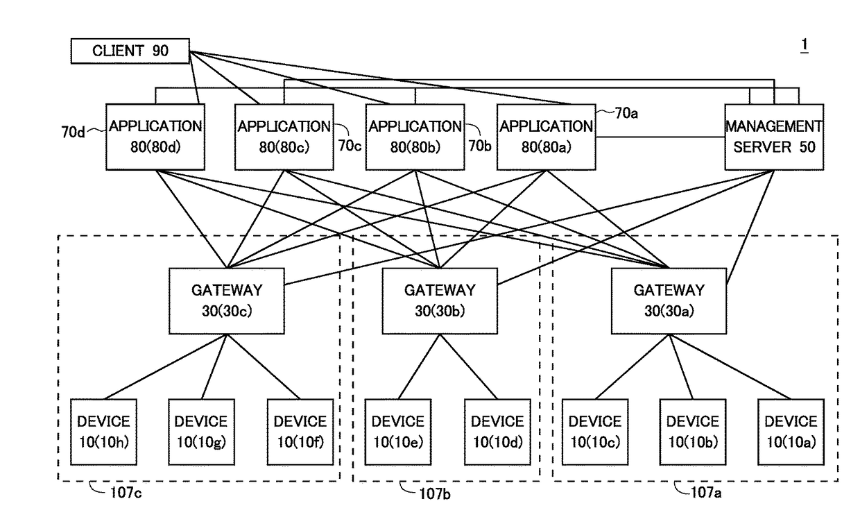
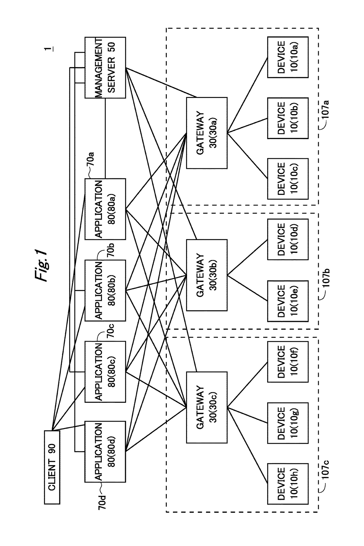
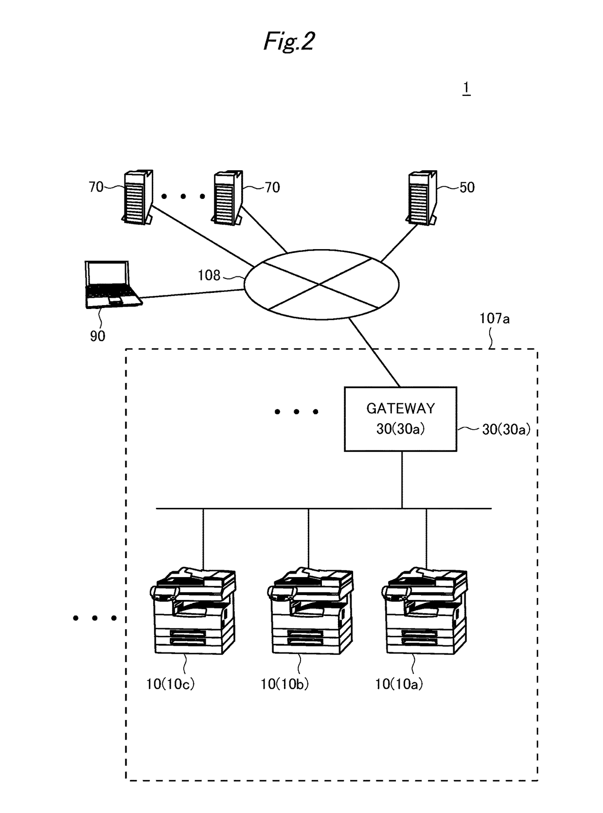
[0038]FIGS. 1 and 2 illustrate a schematic configuration of a communication system 1 according to an embodiment of the present invention. FIG. 2 illustrates part of FIG. 1.

[0039]As illustrated in FIGS. 1 and 2, the communication system 1 includes multiple devices 10 (10a, 10b, 10c, and so on), multiple gateways 30 (30a, 30b, and so on), and a management server computer (hereinafter, also simply referred to as a “management server”) 50. The communication system 1 further includes multiple cloud server computers (hereinafter, also simply referred to as “cloud servers”) 70 and multiple client computers (hereinafter, also simply referred to as “clients”) 90.

[0040]These constituent elements 10, 30, 50, 70, and 90 are connected to one another via a network 108 (see FIG. 2) and can carry out network communication. The network 108 may be configured by local area networks (LANs) 107 and the Internet. A form of connection to the ne...

second embodiment

2. Second Embodiment

[0177]2-1. Overview

[0178]A second embodiment is a variation of the first embodiment. The following description focuses mainly on differences from the first embodiment.

[0179]In the above-described first embodiment, the number of existing connections (the number of established tunnel connections) and the application-specific upper-limit number M are compared for each application, and operations that relate to tunnel connection are controlled on the basis of the comparison result. The present invention is, however, not limited to this example.

[0180]For example, the number of existing connections (the number of established tunnel connections) and a direction-specific upper-limit number (also referred to as a “type-specific upper-limit number”) M0, which will be described later, may be compared for each application and for each direction (in other words, type) of a communication request, which will be described later, and operations that relate to tunnel connection ma...


PUM


Abstract

A communication system includes at least one device, at least one cloud server, and a communication relay device that relays communication between the at least one device and at least one application executed by the at least one cloud server. The communication relay device receives a connection request to establish an individual connection between the communication relay device and one of the at least one application. The communication relay device determines an application-specific upper-limit number and establishes a new individual connection with the application, on condition that the total number of individual connections currently established between the communication relay device and the application is less than the application-specific upper-limit number for the application. In the presence of a high-load application, the communication relay device increases the time interval of requests for communication between the high-load application and the communication relay device.

Description

[0001]This application is based on Japanese Patent Application No. 2016-016135 filed on Jan. 29, 2016, the contents of which are hereby incorporated by reference.BACKGROUND OF INVENTION[0002]Technical Field[0003]The present invention relates to a communication system for carrying out communication between cloud servers outside firewalls and devices inside the firewalls, and to a technique related thereto.[0004]Background Art[0005]There are techniques for interfacing between servers (e.g., cloud servers) outside LANs and devices (e.g., image forming apparatuses) inside the LANs.[0006]One example is a technique for printing out electronic documents stored in servers (cloud servers) in clouds by using image forming apparatuses (e.g., Multi-Functional Peripherals; MFPs) in local area networks (LANs) (see Japanese Patent Application Laid-Open No. 2013-73578).[0007]Japanese Patent Application Laid-Open No. 2013-73578 discloses a document output system (communication system) that includes ...

Claims


Application Information

Patent Timeline
Patent Type & Authority Applications(United States)
IPC IPC(8): H04L29/08
CPCH04L67/141H04L67/10H04L67/28H04L63/02H04L41/0803H04L67/62H04L41/00H04L67/56
Inventor KOUNO, TAKAHIRO
Owner KONICA MINOLTA INC
Why Eureka
Try Eureka