Welding electrode cutting tool and method of using the same

a cutting tool and welding electrode technology, applied in the direction of electrode maintenance, manufacturing tools, electrode features, etc., can solve the problems of plastic deformation, welding aluminum workpieces to steel workpieces, and the welding of welding electrodes is fraught with challenges

Active Publication Date: 2017-08-10
GM GLOBAL TECH OPERATIONS LLC
View PDF1 Cites 25 Cited by
  • Summary
  • Abstract
  • Description
  • Claims
  • Application Information

AI Technical Summary

Benefits of technology

[0018]A method of dressing welding electrodes having asymmetric weld face geometries includes several steps according to one embodiment of the disclosure. In particular, a cutting tool is provided that includes a body and a cutting member within the body. The cutting member comprises one or more cutting flutes that establish a first cutting socket and a second cutting socket. The first cutting socket is accessible through a first opening at a first end of the body and the second cutting socket is accessible through a second opening at a second end of the body. A first weld face of a first welding electrode is received in the first cutting socket and a second weld face of a second welding electrode is received in the second cutting socket. Once the first and second weld faces are received in the first and second cutting sockets, respectively, the cutting tool is rotated to cut and restore a first weld face geometry in the first weld face and a second weld face geometry in the second weld face. The first weld face geometry is different from the second weld face geometry.
[0019]The method of dressing welding electrodes having asymmetric weld face geometries may be practiced with certain preferences. For instance, the cutting tool may be rotated between one and ten full rotations about axes of the first and second weld faces such that a depth of material ranging from 10 μm and 500 μm is removed from each of the first weld face and the second weld face during restoration of the first weld face geometry and the second weld face geometry. Additionally, a set of ten to one hundred weld joints between overlapping and adjacent steel and aluminum workpieces may be formed prior to receiving the first weld face in the first cutting socket of the cutting tool and the second weld face in the second cutting socket of the cutting tool. Many other variations of the resistance spot welding method may of course be practiced.

Problems solved by technology

Over the course of repeated resistance spot welding operations, the weld faces of the welding electrodes are susceptible to degradation due to the large quantity of heat generated at the weld faces during current flow and the high compressive force used to hold the weld faces against the workpiece stack-up.
Such degradation may include plastic deformation of the weld face and / or contamination build-up that results from a reaction between the electrode and its respective contacting workpiece at elevated temperatures.
Resistance spot welding an aluminum workpiece to a steel workpiece is fraught with challenges.
Apart from the need to periodically dress weld faces that undergo different degradation mechanisms, the disparate properties of the two workpieces and the presence of a mechanically tough, electrically insulating, and self-healing refractory oxide layer (or layers) on the aluminum workpiece have made it difficult to consistently achieve weld joints with adequate peel and cross-tension strengths.
Given that previous spot welding efforts have not been particularly successful, mechanical fasteners including self-piercing rivets and flow-drill screws have predominantly been used to fasten aluminum and steel workpieces together.
Mechanical fasteners, however, take longer to install and have high consumable costs compared to spot welding.

Method used


Image

  • Welding electrode cutting tool and method of using the same
  • Welding electrode cutting tool and method of using the same
  • Welding electrode cutting tool and method of using the same

Examples


Embodiment Construction

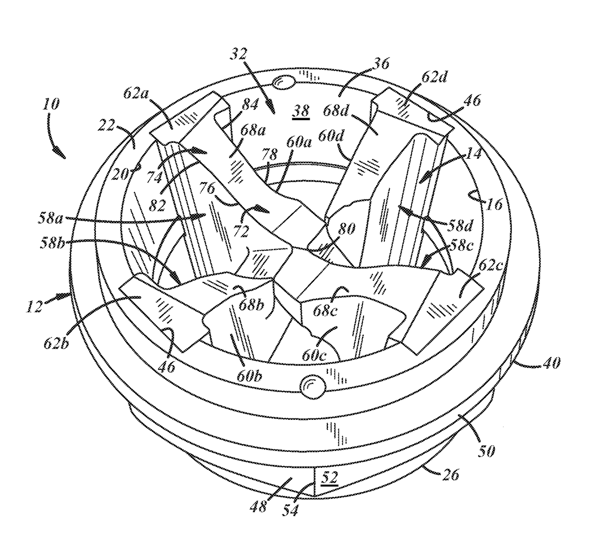
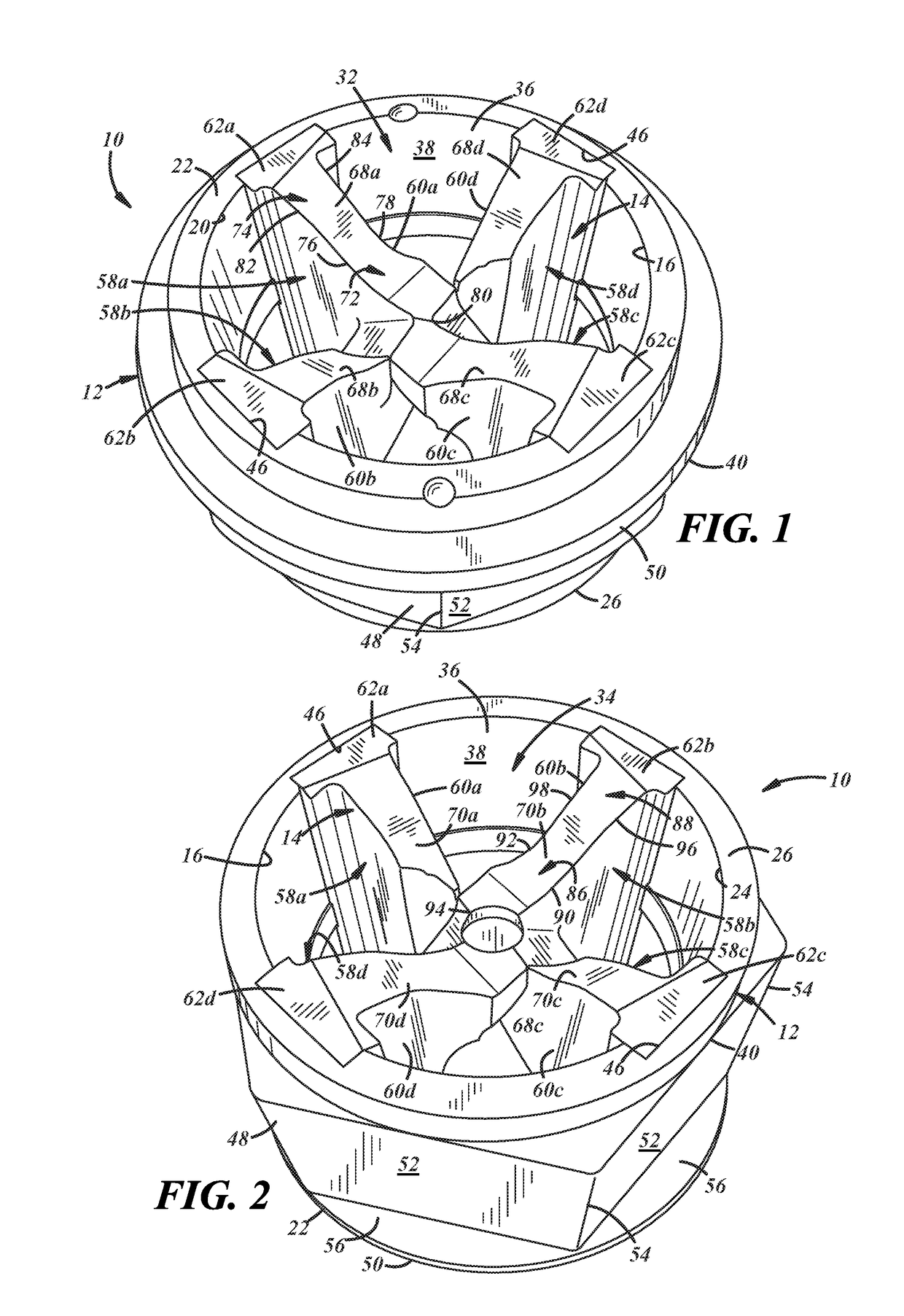
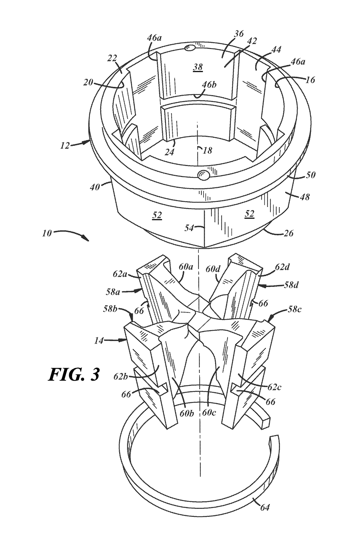
[0046]A cutting tool is disclosed that can simultaneously cut and restore asymmetric weld face geometries of two welding electrodes that are subject to different degradation mechanisms. The cutting tool may be used as part of a method for resistance spot welding a workpiece stack-up that includes adjacent and overlapping steel and aluminum workpieces. In particular, a first welding electrode with a first weld face and a second welding electrode with a second weld face may be employed to pass an electrical current through the workpiece stack-up at a weld site. The geometry of the first weld face and the geometry of the second weld face are asymmetric because of the need to compensate for the different physical properties of the steel and aluminum workpieces. Over time, the first and second weld faces become degraded to such an extent that spot welding operations are adversely affected. To address this issue, the cutting tool can be used to periodically redress both the first and seco...


PUM

PropertyMeasurementUnit
diameteraaaaaaaaaa
diameteraaaaaaaaaa
diameteraaaaaaaaaa

Abstract

A cutting tool that can simultaneously cut and restore asymmetric weld face geometries of two welding electrodes that are subject to different degradation mechanisms is disclosed along with a method of using such a cutting tool during resistance spot welding of workpiece stack-ups that include dissimilar metal workpieces. The cutting tool includes a first cutting socket and a second cutting socket. The first cutting socket is defined by one or more first shearing surfaces and the second cutting is defined by one or more second shearing surfaces. The first shearing surface(s) and the second shearing surface(s) are profiled to cut and restore a first weld face geometry and a second weld face geometry, respectively, that are different from each other upon receipt of electrode weld faces within the cutting sockets and rotation of the cutting tool.

Description

CROSS-REFERENCE TO RELATED APPLICATION(S)[0001]This application claims the benefit of U.S. Provisional Application No. 62 / 291,030, which was filed on Feb. 4, 2016. The aforementioned provisional application is incorporated herein by reference in its entirety.TECHNICAL FIELD[0002]The technical field of this disclosure relates generally to a cutting tool for dressing welding electrodes that are used to resistance spot weld workpiece stack-ups that include dissimilar workpieces such as an aluminum workpiece and an adjacent steel workpiece.BACKGROUND[0003]Resistance spot welding is a process used by a number of industries to join together two or more metal workpieces. The automotive industry, for example, often uses resistance spot welding to join together metal workpieces during the manufacture of structural frame members (e.g., body sides and cross members) and vehicle closure members (e.g., vehicle doors, hoods, trunk lids, and lift-gates), among others. A number of spot welds are of...

Claims


Application Information

Patent Timeline
Patent Type & Authority Applications(United States)
IPC IPC(8): B23K11/30B23B5/16
CPCB23B5/166B23K11/3063B23K11/20Y10T29/5107Y10T409/304256
Inventor SIGLER, DAVID R.CARLSON, BLAIR E.KARAGOULIS, MICHAEL J.SCHROTH, JAMES G.
Owner GM GLOBAL TECH OPERATIONS LLC
Why Eureka
Try Eureka