Oil pump

a technology of oil pump and oil pressure, which is applied in the direction of liquid fuel engines, rotary/oscillating piston pump components, machines/engines, etc., can solve the problems of noise or erosion, failure to produce a sufficient inhibition effect, and noise or erosion, and achieve the effect of rapid oil pressure increas

Inactive Publication Date: 2017-08-10
JTEKT CORP
View PDF2 Cites 2 Cited by
  • Summary
  • Abstract
  • Description
  • Claims
  • Application Information

AI Technical Summary

Benefits of technology

[0009]An object of the invention is to provide an oil pump that is more effective for inhibiting the adverse effect of instantaneous collapse of bubbles resulting from a rapid increase in the pressure of oil in an inter-tooth chamber between an inner rotor and an outer rotor.

Problems solved by technology

This phenomenon is significant when the inter-tooth chamber comes into communication with the discharge port while the pressure in the inter-tooth chamber is not high enough due to many bubbles mixed in the oil.
When the oil at the discharge port flows into the inter-tooth chamber as a jet, the bubbles mixed in the oil in the inter-tooth chamber may instantaneously collapse, leading to noise or erosion.
The oil pumps described in JP 2005-42689 A and JP 2006-266161 A may allow inhibition of the adverse effect (noise or erosion) of collapsing bubbles resulting from, for example, cavitation but may fail to produce a sufficient inhibition effect when the sucked oil contains a large number of bubbles.
That is, the oil at the discharge port may flow into the inter-tooth chamber as a jet causing rapid elevation of the pressure in the inter-tooth chamber, resulting in noise or erosion.

Method used


Image

  • Oil pump
  • Oil pump
  • Oil pump

Examples


Embodiment Construction

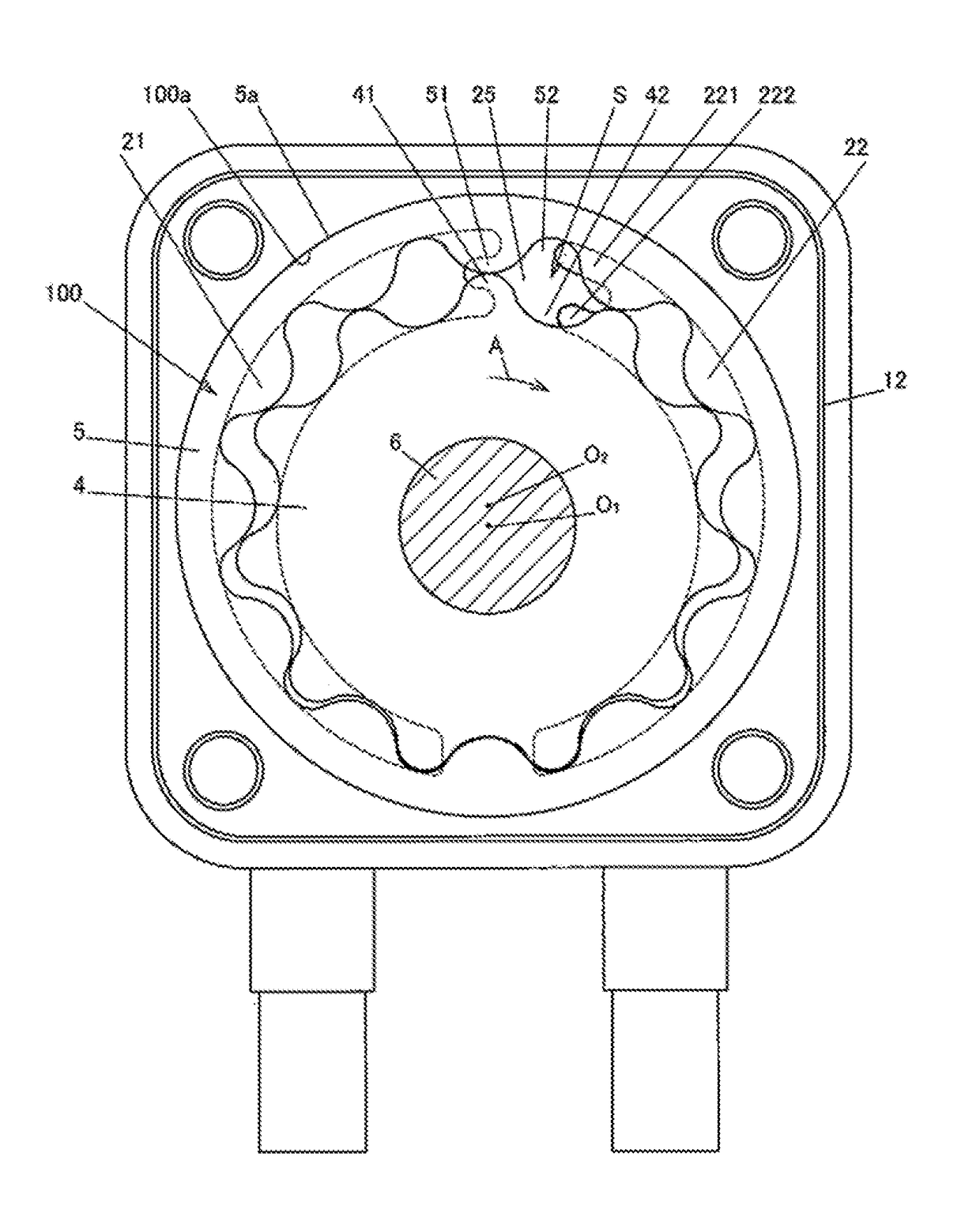
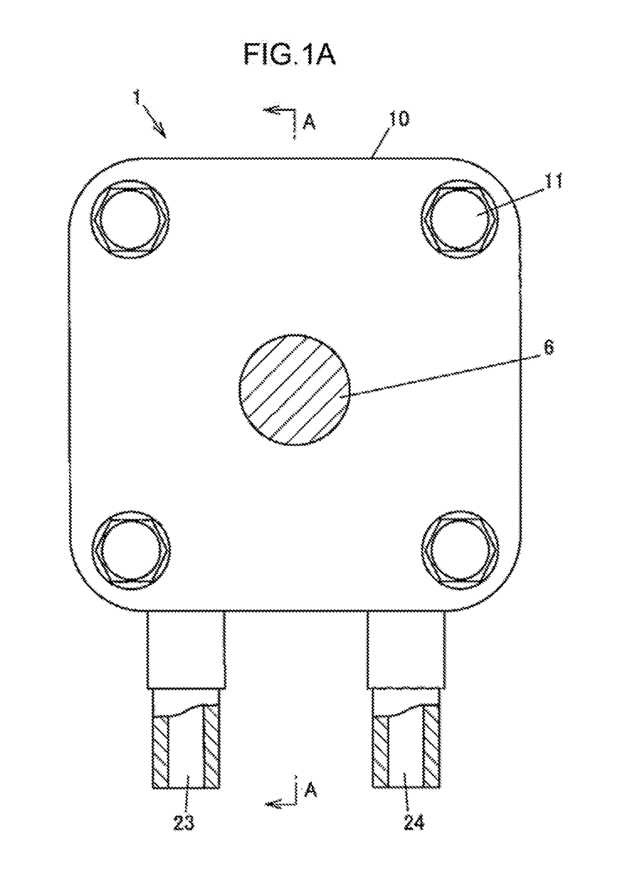
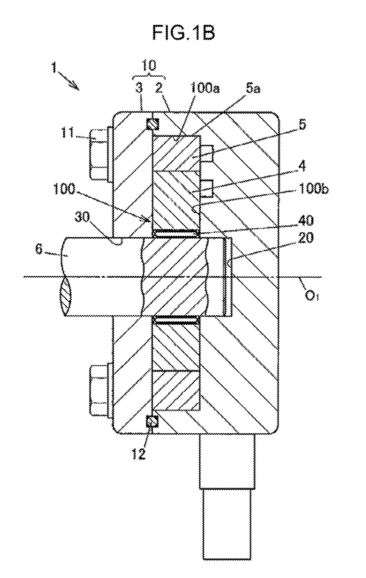
[0020]An embodiment of the invention will be described with reference to FIGS. 1 to 4. FIGS. 1A and 1B depict an oil pump according to an embodiment of the invention. FIG. 1A is a front view, and FIG. 1B is a sectional view taken along line A-A in FIG. 1A. FIG. 2 is a diagram depicting an internal structure of the oil pump. An oil pump 1 is used, for example, to lubricate and operate components of a transmission in an automobile. The oil pump 1 sucks oil from an oil pan in a transmission case and discharges the oil.

[0021]The oil pump 1 is a torochoidal inscribed gear pump and has a pump housing 10 including a main body portion 2 and a cover portion 3, an inner rotor 4 and an outer rotor 5 housed in a pump chamber 100 in the pump housing 10 and having a torochoid tooth profile, and a shaft 6 that applies a turning force to the inner rotor 4. FIG. 2 depicts the oil pump 1 with the cover portion 3 removed therefrom as viewed in an axial direction.

[0022]In the main body portion 2 of the...


PUM


Abstract

In an oil pump, an inner rotor and an outer rotor rotate to discharge the oil through a discharge port. The discharge port has an outer extension portion located on a radially inner side with respect to a root circle of the outer rotor and on a radially outer side of a tip circle of the outer rotor and an inner extension portion located on the radially inner side with respect to the tip circle of the outer rotor and on the radially outer side with respect to a root circle of the inner rotor. An inter-tooth chamber facing a partitioning portion that partitions the suction port from the discharge port comes into communication with the outer extension portion and the inner extension portion. Then, a tip seal portion defining the inter-tooth chamber intersects an outer edge of an opening of the discharge port.

Description

INCORPORATION BY REFERENCE[0001]The disclosure of Japanese Patent Application No. 2016-019730 filed on Feb. 4, 2016 including the specification, drawings and abstract, is incorporated herein by reference in its entirety.BACKGROUND OF THE INVENTION[0002]1. Field of the Invention[0003]The invention relates to an oil pump in which an inner rotor and an outer rotor having a trochoid tooth profile rotate to allow oil sucked into a pump chamber to be discharged out of the pump chamber through a discharge port.[0004]2. Description of the Related Art[0005]An oil pump in which an inner rotor and an outer rotor having a trochoid tooth profile rotate to allow oil sucked into a pump chamber through a suction port to be discharged out of the pump chamber through a discharge port has been used for hydraulic equipment and the like. In such an oil pump, when the discharge port is brought into communication with one of the inter-tooth chambers formed between tooth profile portions of the inner rotor...

Claims


Application Information

Patent Timeline
Patent Type & Authority Applications(United States)
IPC IPC(8): F04C2/10F01M1/02F04C15/06
CPCF04C2/10F04C15/06F04C2240/20F04C2210/206F04C2240/30F01M1/02F04C2/088F04C2/102F16N13/20F01M2001/0238F04C2270/13
Inventor OOWAKI, MASAAKI
Owner JTEKT CORP
Why Eureka
Try Eureka