Cylindrical superconducting magnet coil structure with methods of making and assembling it

Active Publication Date: 2017-08-10
SIEMENS HEALTHCARE LTD
View PDF3 Cites 3 Cited by
  • Summary
  • Abstract
  • Description
  • Claims
  • Application Information

AI Technical Summary

Benefits of technology

[0010]The present invention also seeks to provide a structure and assembly technique that allows the coils to be aligned correctly, and allows for

Problems solved by technology

In any such method where a number of coils are wound and impregnated at the same time, there is a risk that a manufacturing defect in one coil cannot be corrected, resulting in scrapping of the whole impregn

Method used


Image

  • Cylindrical superconducting magnet coil structure with methods of making and assembling it
  • Cylindrical superconducting magnet coil structure with methods of making and assembling it
  • Cylindrical superconducting magnet coil structure with methods of making and assembling it

Examples


Embodiment Construction

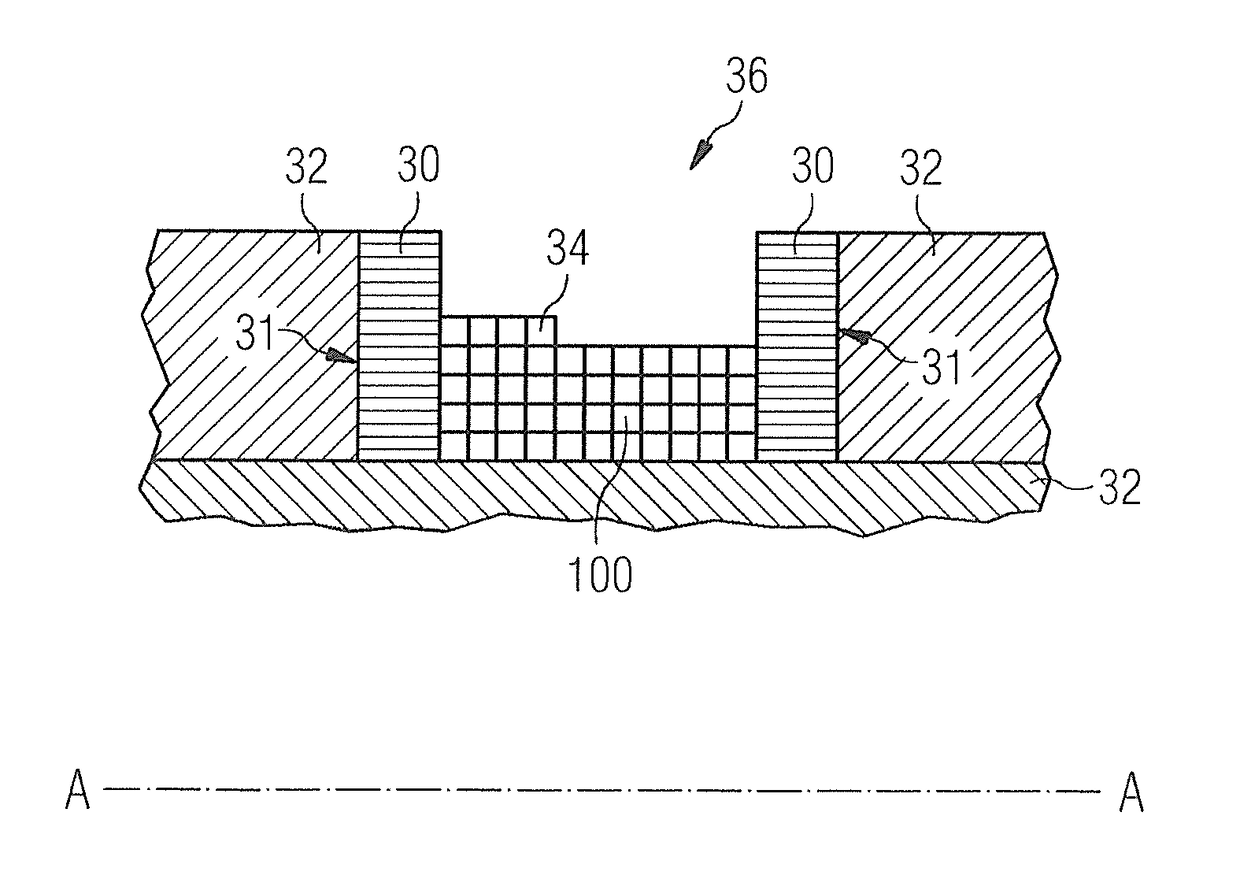
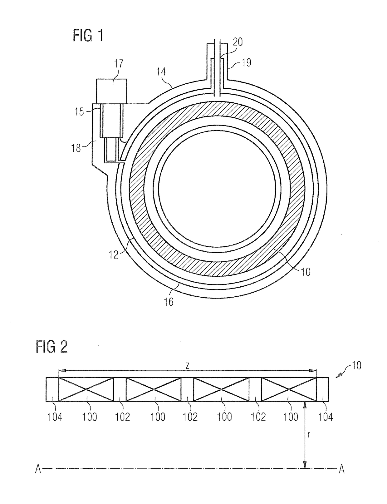
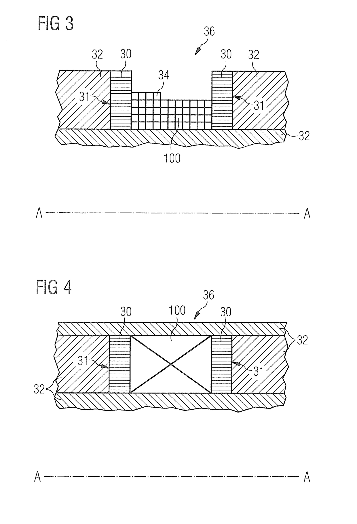
[0023]The present invention relates to serially-bonded coil structures. An example of a serially-bonded coil structure 10 is shown in FIG. 2 as a schematic half-cross-section. The structure is essentially rotationally symmetrical about axis A-A. The terms “radial” and “axial” and similar terms will be used herein to denote directions and dimensions which are respectively: “perpendicular to the axis A-A and extending in a plane which contains the axis A-A”; and “parallel or co-incident with the axis A-A”. Similarly, terms such as “outer” and “inner” refer to relative proximity to the mid-point of axis A-A. Dimension r is typically about 50 cm, and dimension z is typically about 150 cm for an MRI Magnet, and smaller dimensions for a typical NMR magnet. A number of coils 100 of superconducting wire are provided, each impregnated with a material such as a thermosetting resin, as is conventional in itself. Coils 100 are separated by spacers 102. The spacers may be composed of wire, such ...


PUM


Abstract

A cylindrical superconducting coil assembly comprising a plurality of individual coil units stacked together and retained in place by retaining structures, each coil unit comprising a resin-impregnated annular superconducting coil bonded at its axial extremities to respective rings of non-ferromagnetic material.

Description

BACKGROUND OF THE INVENTION[0001]Field of the Invention[0002]The present invention provides cylindrical superconducting magnet coil structures, for example as used in Magnetic Resonance Imaging (MRI) systems. Such magnets must be cooled to below the transition temperature of the superconducting wire used which requires the superconducting magnet coil structure to be placed in a cryostat to isolate it from ambient temperature.[0003]Description of the Prior Art[0004]FIG. 1 shows an example conventional arrangement of a cryostat including a cryogen vessel 12. A superconducting magnet comprises a coil structure 10 within cryogen vessel 12, itself retained within an outer vacuum chamber (OVC) 14. One or more thermal radiation shields 16 are provided in a vacuum space between the cryogen vessel 12 and the outer vacuum chamber 14. In some known arrangements, a refrigerator 17 is mounted in a refrigerator sock 15 located in a turret 18 provided for the purpose, towards the side of the cryos...

Claims


Application Information

Patent Timeline
IPC IPC(8): H01F41/04H01F41/064
CPCH01F41/064H01F41/048G01R33/3802G01R33/3815H01F6/06H01F41/127G01R33/3873H01F41/005
Inventor DAVIS, PETER JONATHANFORD, DAVID WILLIAMLONGFIELD, MATTHEW JOHN
Owner SIEMENS HEALTHCARE LTD
Why Eureka
Try Eureka