Integrated and Combined Phase Shifter and Isolation Switch

a phase shifter and isolation switch technology, applied in the field of electronic radio frequency (rf) circuits, can solve the problems of increasing insertion loss, not fully isolated, adding insertion loss, etc., and achieve good return loss.

Active Publication Date: 2017-08-10
PSEMI CORP
View PDF2 Cites 10 Cited by
  • Summary
  • Abstract
  • Description
  • Claims
  • Application Information

AI Technical Summary

Benefits of technology

[0018]Embodiments of the present invention provide a phase shifter unit cell or a connected set of such cells that can be well isolated from external circuitry and which do not introduce insertion loss into the RF signal path, exhibit good return loss, and further provides additional advantages when combined with bracketing attenuator circuits.
[0019]More particularly, embodiments of the present invention integrate a high-isolation function within a phase shifter circuit that does not introduce added insertion loss and reduces die area compared to a conventional series switch solution. These advantages are accomplished by breaking the complimentary nature of the control signals to a phase shifter cell to provide greater control of switch states internal to the phase shifter cell and thus enable a distinct high-isolation state, and by including a switchable shunt termination resistor for use in the high-isolation state.
[0021]Some embodiments are serially coupled to attenuator circuits to enable synergistic interaction that reduces overall die size and / or increases isolation. One such embodiment positions a phase shifter cell in accordance with the present invention between bracketing programmable attenuators.

Problems solved by technology

A conventional solution would be to insert a FET switch in series with the input of the phase shifter chain—for example, at node X in FIG. 1—but doing so would introduce added insertion loss.
Thus, adding a series FET switch to a phase shifter circuit will increase insertion loss due to the ON resistance, RON, of the FET while remaining capacitively coupled to external circuitry—and thus not fully isolated from the RF signal path—due to the capacitance COFF.

Method used


Image

  • Integrated and Combined Phase Shifter and Isolation Switch
  • Integrated and Combined Phase Shifter and Isolation Switch
  • Integrated and Combined Phase Shifter and Isolation Switch

Examples


first example embodiment

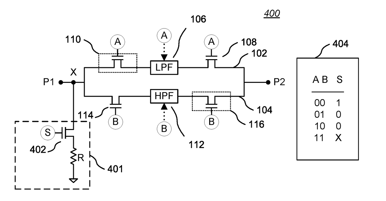
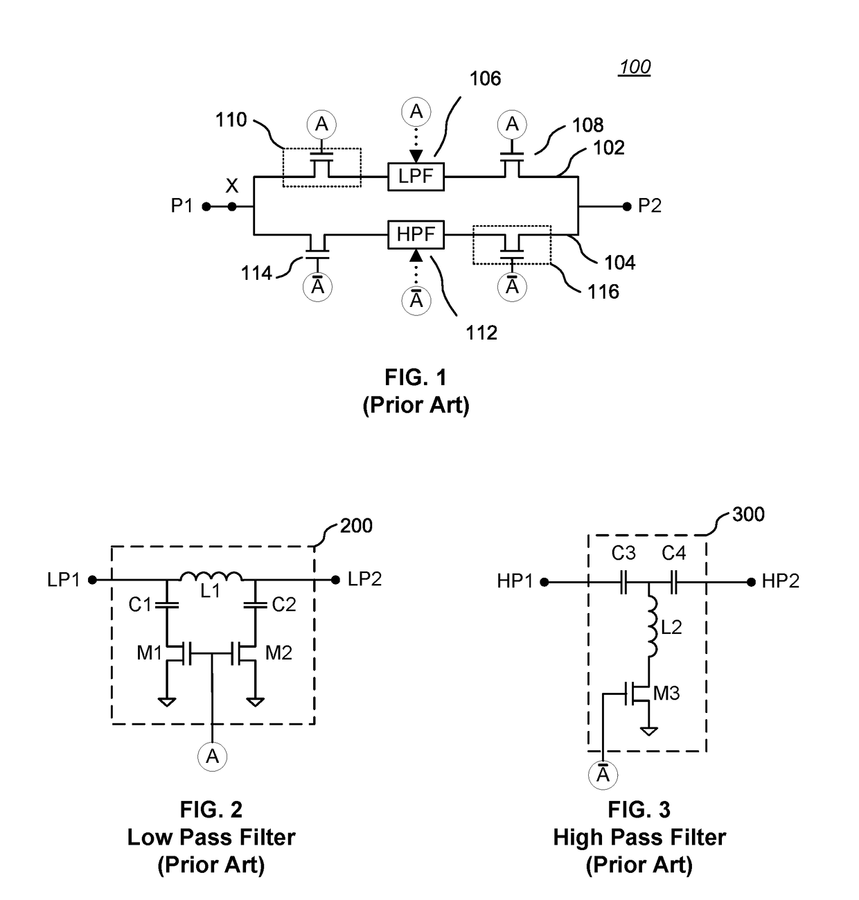
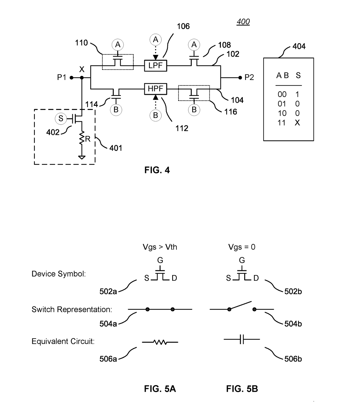
[0041]FIG. 4 is a block diagram of a first embodiment of the present invention showing a phase shifter unit cell 400 having independent path selection control signals A, B, and a distinct isolation circuit control signal S. The components and configuration of the phase shifter cell 400 is similar to the phase shifter unit cell 100 of FIG. 1, but further includes a termination circuit 401 coupled to a node X on the input port (P1 in this example) of the phase shifter unit cell 400.

[0042]In the illustrated embodiment, the termination circuit 401 comprises a shunt resistor R serially coupled to a shunt switch 402, shown as a FET (such as a MOSFET). The order of the shunt resistor R and the shunt switch 402 may be reversed. In some embodiments, the shunt resistor R may be a variable resistor to allow tuning the termination circuit 401 to a particular characteristic impedance (typically 50 ohms for an RF circuit). The shunt switch 402 may be implemented as a “stack” of serially connected...


PUM


Abstract

A phase shifter unit cell or a connected set of such cells that can be well isolated from external circuitry and which do not introduce insertion loss into an RF signal path, exhibit good return loss, and further provides additional advantages when combined with bracketing attenuator circuits. More particularly, embodiments integrate a high-isolation function within a phase shifter circuit by breaking the complimentary nature of the control signals to a phase shifter cell to provide greater control of switch states internal to the phase shifter cell and thus enable a distinct high-isolation state, and by including a switchable shunt termination resistor for use in the high-isolation state. Some embodiments are serially coupled to attenuator circuits to enable synergistic interaction that reduces overall die size and / or increases isolation. One such embodiment positions a high-isolation phase shifter cell in accordance with the present invention between bracketing programmable attenuators.

Description

BACKGROUND[0001](1) Technical Field[0002]This invention relates to electronic radio frequency (RF) circuits, and more particularly to RF phase shifter circuits.[0003](2) Background[0004]Electronic phase shifter circuits are used to change the transmission phase angle of a signal, and are commonly used to phase shift RF signals. RF phase shifter circuits may be used for applications such as in-phase discriminators, beam forming networks, power dividers, linearization of power amplifiers, and phased array antennas, to name a few.[0005]For many applications, it may be useful to serially-connect multiple phase shifter unit cells of the same or different phase shift values. Such phase shifter circuits may be digitally controlled and thus provide a discrete set of phase states that are selected by a binary control word, directly or after decoding. For example, such phase shifter circuits may be binary-coded, thermometer coded, or a hybrid combination of the two types. Some phase shifter c...

Claims


Application Information

Patent Timeline
Patent Type & Authority Applications(United States)
IPC IPC(8): H01P1/18H03H11/24H03H11/18
CPCH03H11/18H03H11/245H03H7/20
Inventor SHAPIRO, ERIC S.BACON, PETER
Owner PSEMI CORP
Why Eureka
Try Eureka