Devices and systems for docking a heart valve

a heart valve and device technology, applied in the field of heart valves, can solve the problems of heart valves being rendered less effective, heart valves being too small to secure into the larger implantation or deployment site, serious cardiovascular compromise or death, etc., and achieve the effect of improving retention

Active Publication Date: 2017-08-17
EDWARDS LIFESCIENCES CORP
View PDF1 Cites 88 Cited by
  • Summary
  • Abstract
  • Description
  • Claims
  • Application Information

AI Technical Summary

Benefits of technology

[0014]In one exemplary embodiment, a method can include expanding a docking station and expanding a valve in the docking station. The docking station can be expanded such that a valve seat of the docking station expands to a valve seat deployed size and a sealing portion expands to a sealing size that is within a range of sealing sizes. A frame of an expandable valve can be expanded to engage the valve seat of the docking station. A pressure of blood acting on the valve and docking station can enhance retention by the retaining portions at the deployed position. The valve seat of the docking station can be configured such that a diameter of the valve seat is not increased more than 2 mm (or not more than 1 mm, 3 mm, or 4 mm) by the radial outward force applied by the expandable frame to the valve seat. The range of sealing sizes of the docking station can be from 27 mm to 38 mm. The valve seat can be formed by a suture, ring, band, structural arrangement, material, foam, and in other ways. Other features / steps described elsewhere in this disclosure may also be included.

Problems solved by technology

These heart valves can be rendered less effective by congenital, inflammatory, or infectious conditions.
Such conditions can eventually lead to serious cardiovascular compromise or death.
However, with larger native valves, blood vessels, and grafts, aortic transcatheter valves might be too small to secure into the larger implantation or deployment site.
In this case, the transcatheter valve may not be large enough to sufficiently expand inside the native valve or other implantation or deployment site to be secured in place.
Replacing the pulmonary valve, which is sometimes referred to as the pulmonic valve, presents significant challenges.
Typically, the pulmonary artery outflow tract after corrective surgery is too wide for effective placement of a prosthetic heart valve.

Method used


Image

  • Devices and systems for docking a heart valve
  • Devices and systems for docking a heart valve
  • Devices and systems for docking a heart valve

Examples


Embodiment Construction

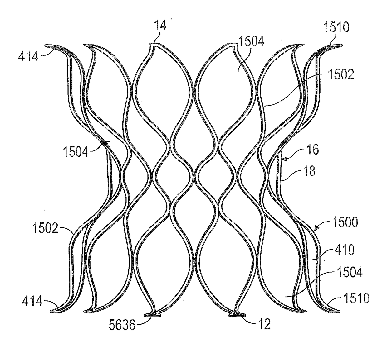
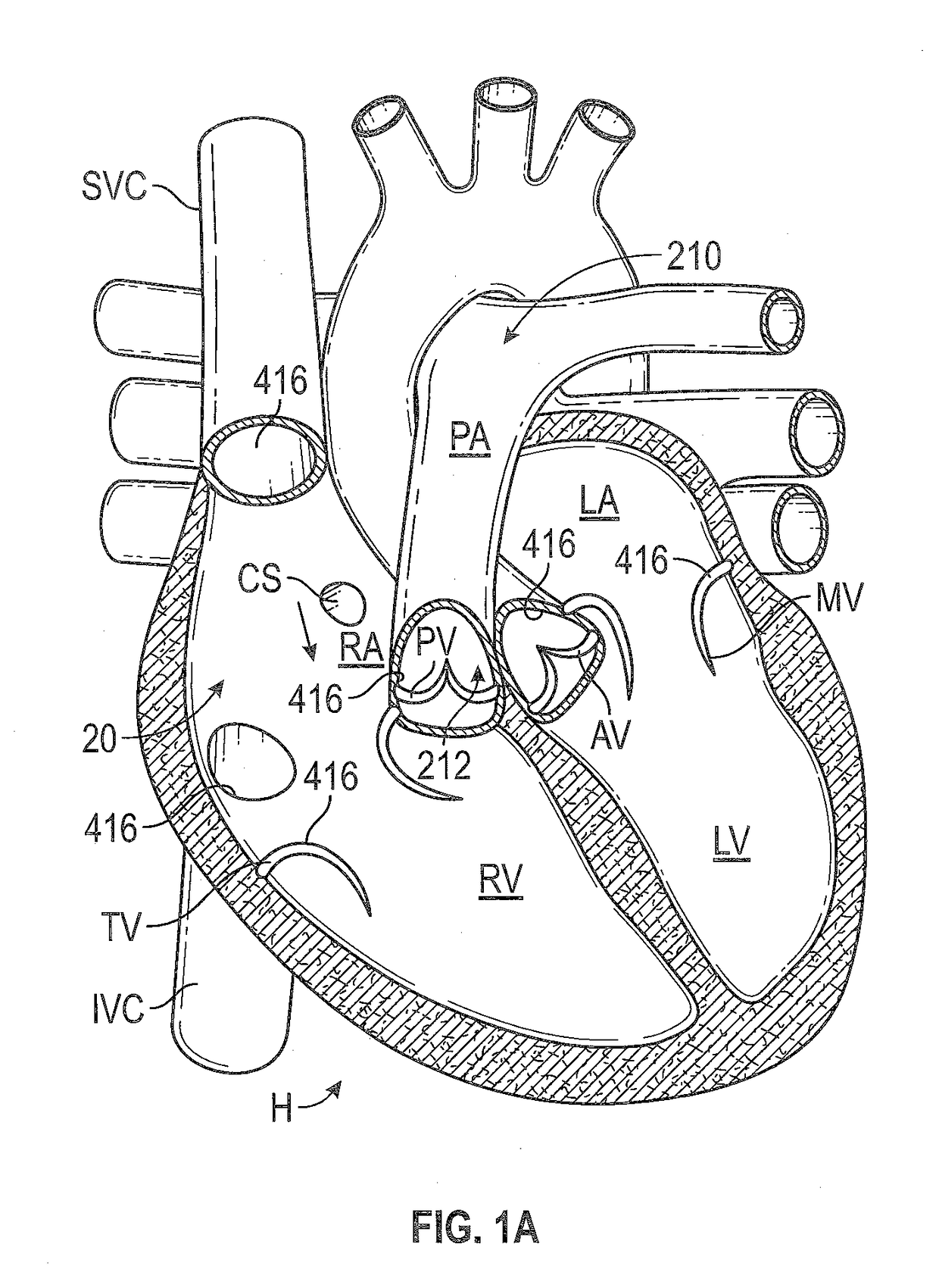
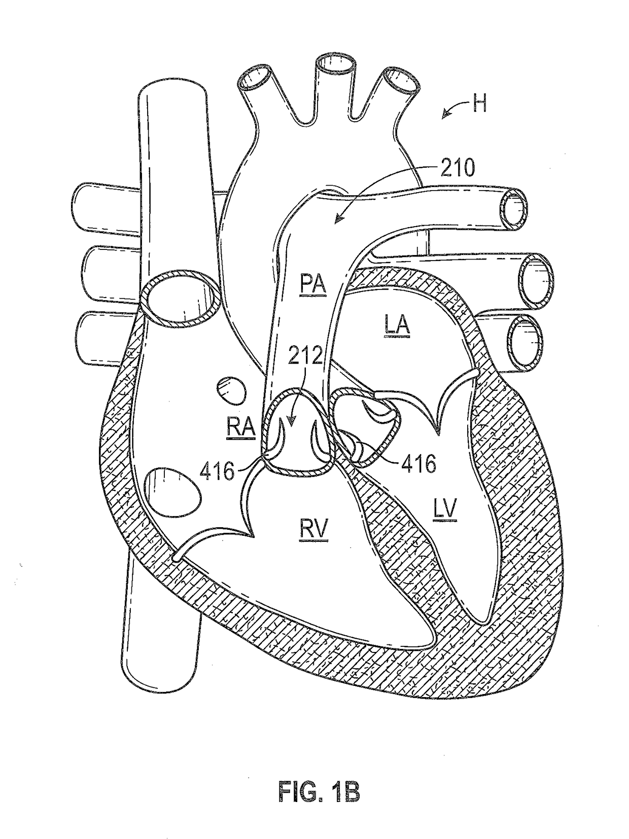
[0147]The following description refers to the accompanying drawings, which illustrate specific embodiments of the invention. Other embodiments having different structures and operation do not depart from the scope of the present invention. Exemplary embodiments of the present disclosure are directed to devices and methods for providing a docking station or landing zone for a transcatheter heart valve (“THV”), e.g., THV 29. In some exemplary embodiments, docking stations for THVs are illustrated as being used within the pulmonary artery, although the docking stations (e.g., docking station 10) may be used in other areas of the anatomy, heart, or vasculature, such as the superior vena cava or the inferior vena cava. The docking stations described herein can be configured to compensate for the deployed THV being smaller than the space (e.g., anatomy / vasculature / etc.) in which it is to be placed.

[0148]It should be noted that various embodiments of docking stations and systems for delive...


PUM


Abstract

Expandable docking stations for docking an expandable valve can include a valve seat, one or more sealing portions, and one or more retaining portions. The valve seat can be unexpandable or substantially unexpandable beyond a deployed size. The one or more sealing portions are connected to the valve seat and extend radially outward of the valve seat. The one or more sealing portions are constructed to expand outward of the valve seat and provide a seal over a range of sizes. The one or more retaining portions are connected to the one or more sealing portions. The one or more retaining portions are configured to retain the docking station at a deployed position.

Description

RELATED APPLICATIONS[0001]The present application claims the benefit of U.S. provisional application Ser. No. 62 / 292,142, filed on Feb. 5, 2015. U.S. provisional application Ser. No. 62 / 292,142 is incorporated herein by reference in its entirety.FIELD OF THE INVENTION[0002]The present invention relates to heart valves and, in particular, docking stations / stents, delivery systems, and methods for use in implanting a heart valve, e.g., a transcatheter heart valve (“THV”).BACKGROUND OF THE INVENTION[0003]Prosthetic heart valves can be used to treat cardiac valvular disorders. The native heart valves (the aortic, pulmonary, tricuspid and mitral valves) serve critical functions in assuring the forward flow of an adequate supply of blood through the cardiovascular system. These heart valves can be rendered less effective by congenital, inflammatory, or infectious conditions. Such conditions can eventually lead to serious cardiovascular compromise or death. For many years the definitive tr...

Claims


Application Information

Patent Timeline
Patent Type & Authority Applications(United States)
IPC IPC(8): A61F2/24
CPCA61F2/2409A61F2/2418A61F2220/0075A61F2220/0008A61F2/2436A61F2/2427A61F2/2442A61F2250/006A61F2250/0069A61F2/9517A61F2/2475A61F2/24
Inventor ARMER, DUSTIN P.FRANKLIN, MICHAEL D.DELGADO, SERGIOJOSHI, ABHIJEETSIRIMANNE, DINESH L.JOSEPH, RUSSELL T.ABBOTT, EASON MICHAELNGUYEN, TRAM NGOCNGUYEN, SON V.NGO, HIEN TRANTRAN, VIVIANBOWMAN, CHARLES L.ROWE, STANTON J.
Owner EDWARDS LIFESCIENCES CORP
Why Eureka
Try Eureka