Light emitting diode luminaire

Inactive Publication Date: 2017-08-17
SHENZHEN YAORONG TECH
View PDF13 Cites 7 Cited by
  • Summary
  • Abstract
  • Description
  • Claims
  • Application Information

AI Technical Summary

Benefits of technology

[0027]7) The installment of a lighting arrester increases safety a

Problems solved by technology

The structure of a typical Light Emitting Diode (LED) luminaire in the art is not convenient for air convection, nor for timely discharge of hot-air, thus suffering from poor heat dissipation.
I

Method used


Image

  • Light emitting diode luminaire
  • Light emitting diode luminaire
  • Light emitting diode luminaire

Examples


Example

[0036]In order to better understand the invention, the invention is further described with reference to the figures and certain embodiments.

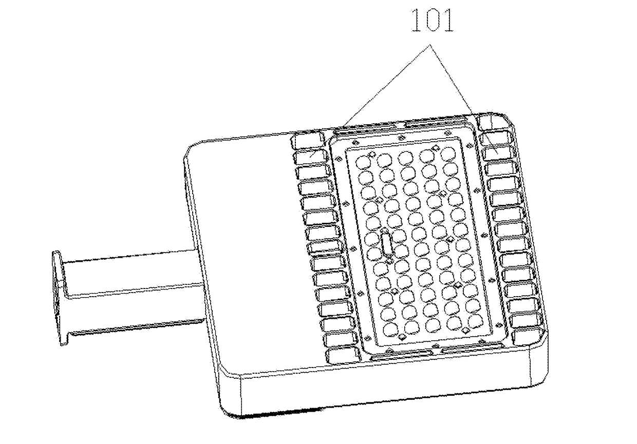
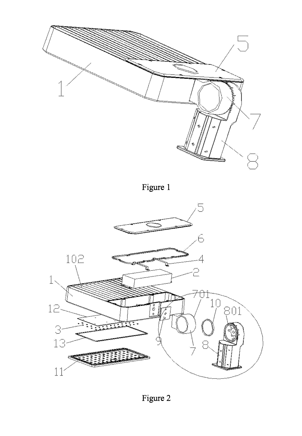
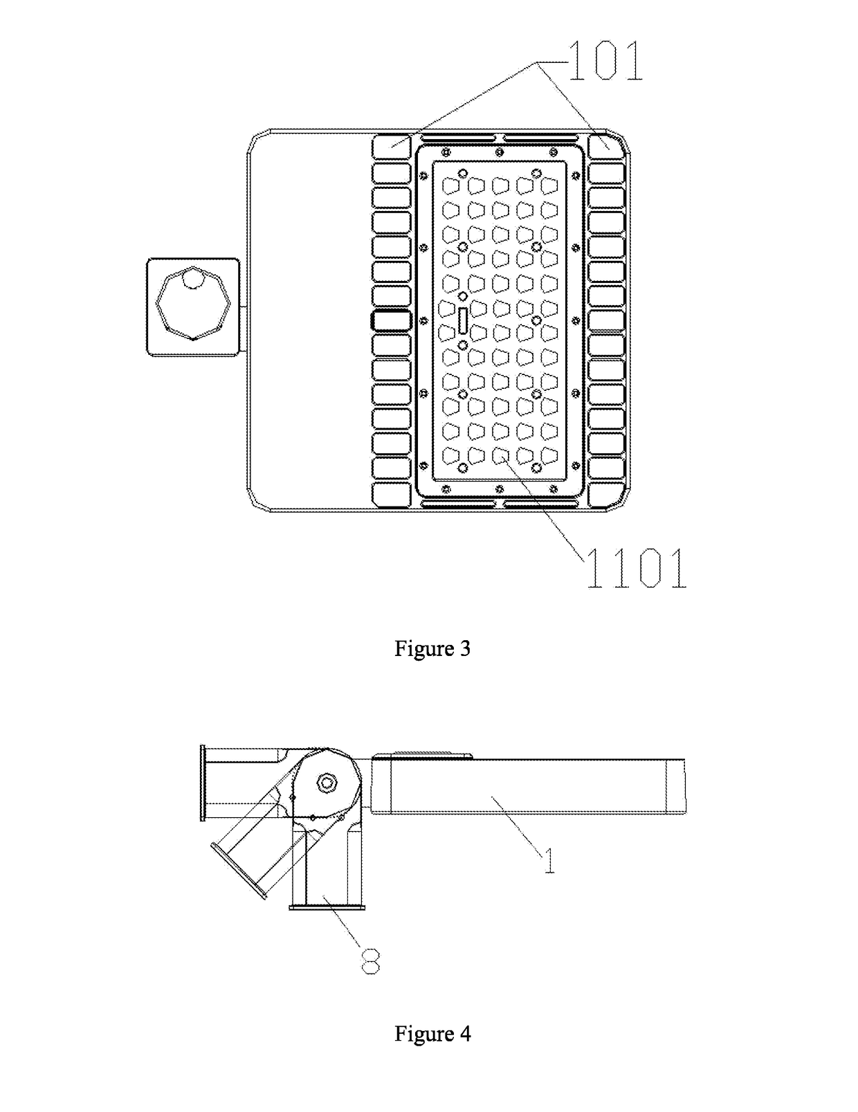
[0037]Referring to FIG. 1, FIG. 2, FIG. 3 and FIG. 4, a Light Emitting Diode luminaire comprises a radiator 1, a power source 2, and a plurality of Light Emitting Diode light sources 3. The power source 2 is electrically connected with the Light Emitting Diode light sources 3. The power source 2 is installed on the radiator 1, can be fixed by a power strip 4, and is covered by a cover of a power box 5 and a silicone ring of power box 6. The radiator 1 is equipped with through-holes 101 from top to bottom, facilitating air convection and air exchange, achieving good heat dissipation effect. The radiator 1 can have a number of heat sinks 102, with gaps in between, allowing for quick heat dissipation. The material of the radiator 1 can be aluminum or copper, for even better heat dissipation effect.

[0038]The Light Emitting Diode luminaire further co...


PUM


Abstract

A Light Emitting Diode (LED) luminaire comprises a heat radiator, a power source and a plurality of LED light sources. The LED luminaire is further equipped with an adapter assembly, one end of which is fixed on the heat radiator and when in use the other end of which is fixed with the outside. The adapter assembly comprises a first adapter and a second adapter which can be rotatably engaged with each other through tooth structures formed on the two adapters; and when the two adapters are engaged to each other through the teeth structures the two adapters together form a waterproof housing. The LED luminaire further comprises a lens module board comprising a plurality of lenses covering the Light Emitting Diode light sources. The lenses comprise light distribution lenses configured to distribute light emitted from the Light Emitting Diode light sources in an asymmetric illumination profile.

Description

CROSS REFERENCE TO RELATED APPLICATIONS[0001]The present application claims priority to Chinese Utility Model CN201420306371.8 filed on Jun. 9, 2014. The present application is the Continuation-in-Part of U.S. patent application Ser. No. 14733941 filed Jun. 8, 2015.TECHNICAL FIELD[0002]The present invention relates to the field of luminaire and especially to an Light Emitting Diode (LED) luminaire.BACKGROUND ART[0003]The structure of a typical Light Emitting Diode (LED) luminaire in the art is not convenient for air convection, nor for timely discharge of hot-air, thus suffering from poor heat dissipation.[0004]In addition, the overall structure is fixed and it is not possible or convenient to adjust the angle of installation.[0005]Furthermore, the lenses of the LED luminaire the art are individual ones, with a glass panel separating the lenses from the outside. Though the purpose of waterproofing is achieved, the structure is not simple.SUMMARY[0006]To address the above mentioned d...

Claims


Application Information

Patent Timeline
IPC IPC(8): F21V29/70F21V5/08F21V15/00F21V31/00F21V23/02F21V5/00F21V29/89
CPCF21V29/70F21V5/007F21V5/08F21V29/89F21V21/30F21V23/02F21V15/00F21Y2115/10F21V31/005F21V5/04F21V29/83F21Y2105/10
Inventor YU, HUANHUANYONG, YING
Owner SHENZHEN YAORONG TECH
Why Eureka
Try Eureka