Coaxially Arranged Mode Converters

a converter and coaxial arrangement technology, applied in the direction of subaqueous/subterranean adaption, baseband system details, borehole/well accessories, etc., can solve the problems of ineffective resonant antennas of concentrated type, ineffective resonant antennas in distributing radiation along the well,

Active Publication Date: 2017-08-17
ENI SPA
View PDF1 Cites 4 Cited by
  • Summary
  • Abstract
  • Description
  • Claims
  • Application Information

AI Technical Summary

Benefits of technology

[0036]According to a preferred embodiment of the present invention, the use of coaxially arranged mode converters for RF heating in oil wells provides various advantages, including the possibility of distributing the RF energy over long drain sections, providing uniform RF heating of long drain sections, adapting the radiation behaviour of an array of this kind as a function of the electromagnetic characteristics of the surrounding medium, and forming an antenna of limited bulk for installation in producing wells.
[0037]The systems according to the present invention enable the formation of a distributed antenna having electromagnetic performance (total radiation efficiency, profile of distribution of radiation along the drain and return loss) suitable for the possible applications.

Problems solved by technology

The systems of the prior art have limitations and practical disadvantages, as summarised below.
The resonant antennas of the concentrated type are not effective with horizontal wells having very long drains (for example having a length in the order of hundreds of metres).
This is because resonant antennas cannot be effective in distributing radiation along the well, even if they have lengths typical of the drains concerned.
Thus, it is not possible to utilise this class of antenna to distribute energy along the drain.
The parameters of triaxial antennas do not allow the configuration or design of the radiating array to be a function of the characteristics of the surrounding medium or of the desired distribution of energy along the drain.
Furthermore, triaxial antennas may be very bulky constructions, given the need for sleeve constructions surrounding the transmission line.
This last aspect may constitute a disadvantage for incorporating antennas into oil wells.
The first of these arises from the fact that the two-wire line has high losses when transferring energy.
This could result in a marked loss of energy inside the oil well, which is disadvantageous for the transfer of energy deep within the reservoir.
Furthermore, and similarly to triaxial antennas, it is not clear how the distribution of power transferred to the medium may be controlled.

Method used


Image

  • Coaxially Arranged Mode Converters
  • Coaxially Arranged Mode Converters
  • Coaxially Arranged Mode Converters

Examples


Embodiment Construction

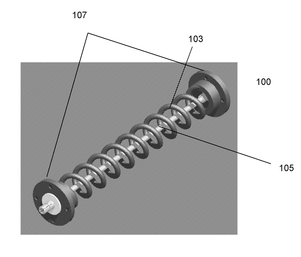
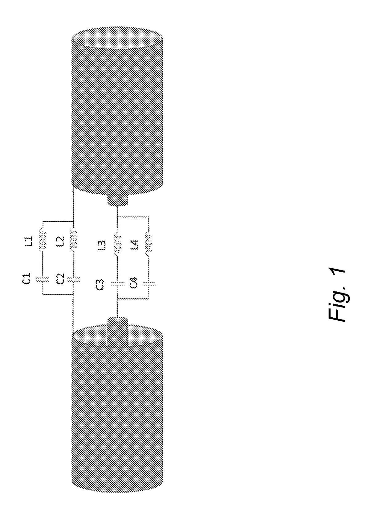
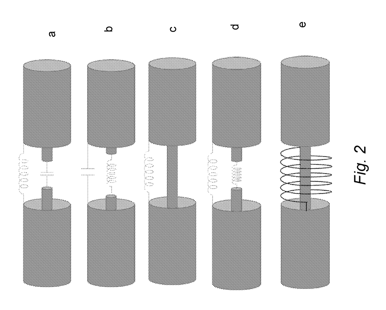
[0042]According to an embodiment of the present invention, the device includes electrical constructions which may be used as mode converters for the formation of the RF antenna in the well. A system for heating the wells by means of a coaxial antenna to which the (one or more) devices according to the present invention may be applied is for example described in the patent application filed, in parallel with the present one, by the same applicant.

[0043]The system operates by applying power in the order of 100-1000 kW at frequencies in the range of 0.1-10 MHz. An embodiment according to these parameters may be advantageous in achieving moderate heating along a drain in the order of several hundred metres in length, such as 1000 m or more. An embodiment of this kind may increase the productivity of a heavy oil well to a significant extent, at the same time ensuring a limited expenditure of energy per barrel of oil produced. In an embodiment of this kind, the increase in temperature may...


PUM


Abstract

The present invention relates to a device for generating a disturbance in the differential mode of propagation of an RF signal transmitted along a coaxial transmission line.

Description

FIELD OF THE INVENTION[0001]The present invention relates to a device for generating a disturbance in the differential mode of propagation of an RF (radio frequency) signal transmitted along a coaxial transmission line.[0002]In particular, a device of this kind is used in a system for the in-situ heating of high-viscosity hydrocarbons by means of RF radiation, particularly a system for creating disturbance along an antenna comprising a coaxial array made up of mode converters, more particularly an RF system comprising a coaxial array of mode converters, inserted in a system for the distributed heating of high-viscosity oils.PRIOR ART[0003]The device of the present invention may be used where there is a need to generate a disturbance in the differential mode of propagation of an RF signal transmitted along a coaxial transmission line.[0004]In particular, the device of the present invention is used in the area of extracting hydrocarbons by means of heating the hydrocarbons themselves ...

Claims


Application Information

Patent Timeline
Patent Type & Authority Applications(United States)
IPC IPC(8): H01Q1/04H01Q13/20H04L25/02E21B43/24
CPCH01Q1/04E21B43/2401E21B43/11H04L25/0272H01Q13/203E21B36/04
Inventor DI RENZO, DOMENICOMALIARDI, ALBERTOGALGANI, GIOVANNI
Owner ENI SPA
Why Eureka
Try Eureka