Liquid ejection apparatus, liquid ejection method, and liquid ejection head

a technology of liquid ejection and liquid ejection, which is applied in the direction of printing, etc., can solve the problems of defective image, degraded ink ejection performance from ejection opening, and disturbed ink flow, so as to suppress the increase in the size of waste liquid tanks and reduce liquid consumption. , the effect of increasing the volume of the waste liquid tank

Active Publication Date: 2017-08-24
CANON KK
View PDF6 Cites 17 Cited by
  • Summary
  • Abstract
  • Description
  • Claims
  • Application Information

AI Technical Summary

Benefits of technology

[0009]An object of the invention is to provide a liquid ejection apparatus, a liquid ejection printing method, and a liquid ejection head capable of decreasing a liquid consumption amount and suppressing an increase in size of a waste liquid tank by causing a deaerated liquid to flow after a recovery operation to remove bubbles inside a passage.

Problems solved by technology

In a case where the gas dissolved in the ink becomes bubbles and the bubbles grow inside the passage or the liquid ejection head, the flow of the ink is disturbed or the ink ejection performance from an ejection opening is degraded, whereby a defective image is obtained.
In a case where the worst condition involving with the generation of bubbles of the ink is supposed and the recovery operation interval is set to prevent an ejection failure even in such a condition, since the frequency of performing the suction recovery operation increases, a problem arises in that a waste ink amount increases.
However, even when a suction recovery process or the like is performed in a case where the printing head is first driven after the installation of the inkjet printing apparatus, there is a possibility that bubbles may remain while not being sufficiently removed from the printing head or the ink passage.
Then, there is a high possibility that the remaining bubbles may grow due to permeation from resin and a formation from saturated ink.
When the frequency of performing the recovery operation increases, a waste ink amount increases.
Accordingly, a running cost caused by the consumption of the ink increases and the capacity of the waste ink tank needs to be increased.

Method used


Image

  • Liquid ejection apparatus, liquid ejection method, and liquid ejection head
  • Liquid ejection apparatus, liquid ejection method, and liquid ejection head
  • Liquid ejection apparatus, liquid ejection method, and liquid ejection head

Examples


first embodiment

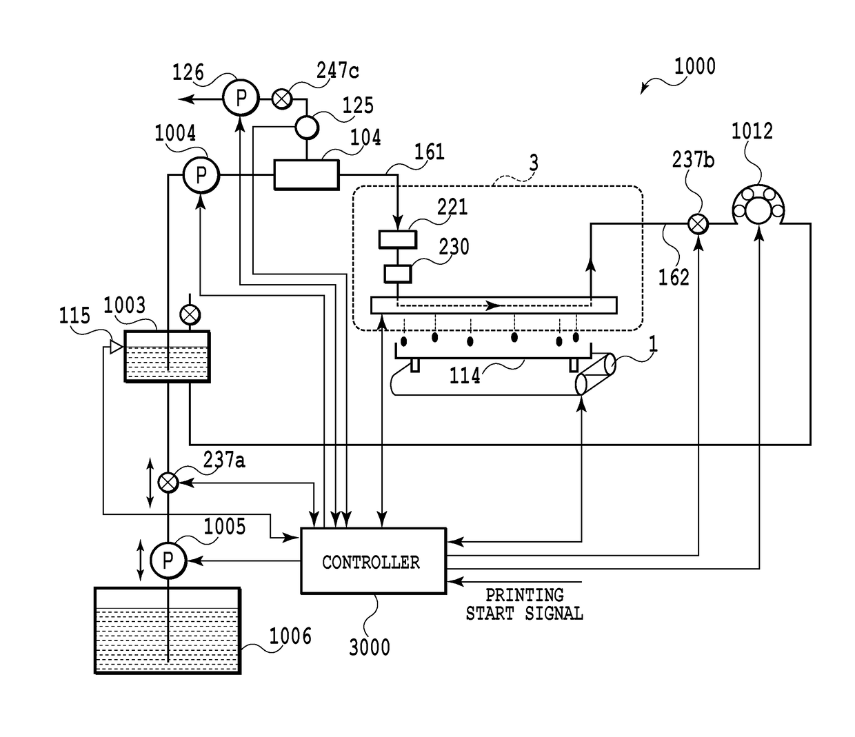
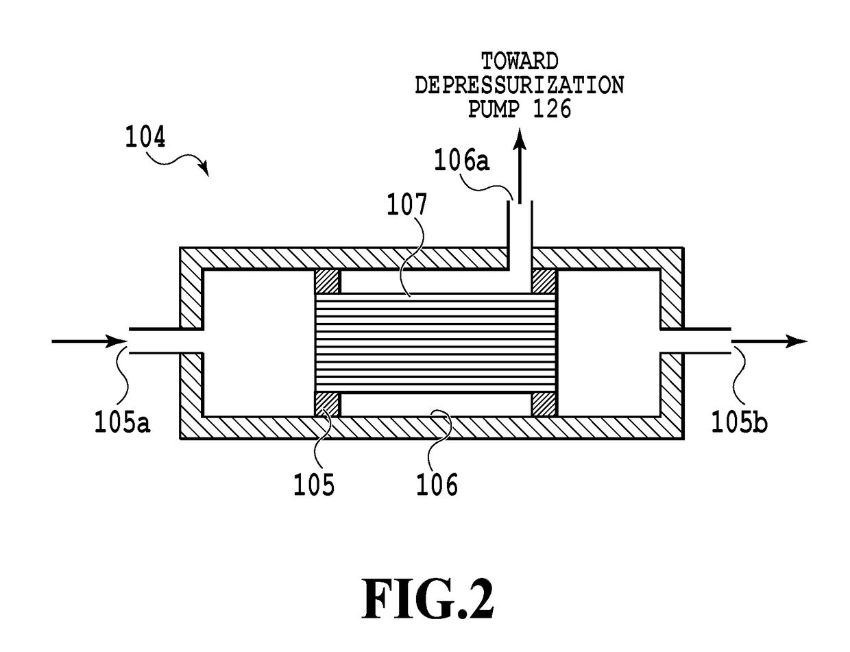
[0049]FIG. 1 is a side view illustrating a schematic configuration of a liquid ejection apparatus of an embodiment of the invention. The liquid ejection apparatus illustrated herein configures an inkjet printing apparatus (hereinafter, referred to as a printing apparatus) 1000 which ejects ink to perform a printing operation. The printing apparatus according to the embodiment can be applied to a printer, a copying machine, a facsimile having a communication system, a word processor having a printer, and an industrial printing apparatus combined with various processing devices. For example, the printing apparatus can be used to manufacture a biochip or print an electronic circuit.

[0050]The printing apparatus 1000 includes a conveying unit 1 which conveys a printing medium 2, a line type liquid ejection head 3 which is disposed to be substantially orthogonal to a conveying direction of the printing medium 2, a liquid supply unit which supplies a liquid such as ink to the liquid ejecti...

second embodiment

[0070]Next, a second embodiment of the invention will be described. FIG. 5 is a side view illustrating a schematic configuration of a liquid ejection apparatus according to the second embodiment. Additionally, in FIG. 5, the same reference numerals will be given to the same or similar components as or to those of the first embodiment and a repetitive description thereof will be omitted. A liquid ejection apparatus 2000 of the second embodiment includes a deaeration tank 1023 which serves as a deaeration unit different from the first embodiment in which the deaeration module is provided as the deaeration unit. Since the deaeration module 104 which is generally used is relatively expensive in structure, there is a possibility that the cost of the deaeration unit in the entire cost of the small-size apparatus may increase too much. Here, in the embodiment, in order to construct a deaeration system at low cost, the deaeration tank 1023 which stores the ink supplied to the liquid ejectio...

third embodiment

[0091]Next, a third embodiment of the invention will be described. A liquid ejection apparatus of the third embodiment is configured to cause the inside an ejection opening formed in a liquid ejection head to flow. Hereinafter, the liquid ejection apparatus of the embodiment will be described in detail below.

(Description of Inkjet Printing Apparatus)

[0092]FIG. 11 is a diagram illustrating a schematic configuration of a liquid ejection apparatus that ejects a liquid in the invention and particularly an inkjet printing apparatus (hereinafter, also referred to as a printing apparatus) 1000 that prints an image by ejecting ink. The printing apparatus 1000 includes a conveying unit 1 which conveys a print medium 2 and a line type (page wide type) liquid ejection head 3 which is disposed to be substantially orthogonal to the conveying direction of the print medium 2. Then, the printing apparatus 1000 is a line type printing apparatus which continuously prints an image at one pass by eject...


PUM


Abstract

The liquid ejection apparatus includes a circulation unit configured to circulate a liquid along a circulation passage extending from a liquid supply source to the liquid supply source through a liquid ejection head. Further, the liquid ejection apparatus includes a deaeration unit configured to perform a deaeration operation of decreasing a dissolved gas amount of the liquid, a recovery unit configured to recover ejection performance of an ejection opening, and a control unit configured to control an operation of driving the circulation unit and the deaeration unit. The control unit starts the deaeration operation and circulates the liquid having been deaerated by the deaeration operation inside a circulation path after the recovery operation and before an initial printing operation after the recovery operation.

Description

BACKGROUND OF THE INVENTION[0001]Field of the Invention[0002]The present invention relates to a liquid ejection apparatus including a liquid supply unit supplying a liquid to a liquid ejection head including an ejection opening ejecting a liquid droplet and also relates to a liquid ejection method and a liquid ejection head.[0003]Description of the Related Art[0004]As a recent liquid ejection apparatus, there is known an inkjet printing apparatus which forms an image by ejecting a liquid including a color material or a liquid (hereinafter, referred to as ink) such as a treatment liquid for adjusting quality of an image to be printed. In the inkjet printing apparatus, a predetermined amount of a gas is normally dissolved in the ink inside a liquid ejection head or an ink passage connected to the liquid ejection head. In a case where the gas dissolved in the ink becomes bubbles and the bubbles grow inside the passage or the liquid ejection head, the flow of the ink is disturbed or the...

Claims


Application Information

Patent Timeline
Patent Type & Authority Applications(United States)
IPC IPC(8): B41J2/19B41J2/185B41J2/17B41J2/195
CPCB41J2/19B41J2/195B41J2002/1853B41J2/1707B41J2/185B41J2/175B41J2/18
Inventor KARITA, SEIICHIROIWANAGA, SHUZOYAMADA, KAZUHIROAOKI, TAKATSUNAOKUSHIMA, SHINGOSAITO, AKIOYAMAMOTO, AKIRATAMENAGA, ZENTARONAGAI, NORIYASUMORI, TATSUROU
Owner CANON KK
Why Eureka
Try Eureka