Method for treating exhaust gas containing elemental fluorine

a fluorine-based exhaust gas and fluorine-containing technology, applied in the direction of separation processes, dispersed particle separation, chemistry apparatus and processes, etc., can solve the problems of high running cost, high toxicity, and the inability to remove oxygen difluoride once generated by water or alkaline aqueous solution, so as to reduce toxic fluorine-based gases, reduce fluorine-based gases, and efficient treatment of fluorine-containing exhaust gas

Inactive Publication Date: 2021-06-03
SHOWA DENKO KK
View PDF0 Cites 0 Cited by
  • Summary
  • Abstract
  • Description
  • Claims
  • Application Information

AI Technical Summary

Benefits of technology

[0025]The method for treating a fluorine element-containing exhaust gas according to the present invention can efficiently treat the fluorine element-containing exhaust gas by a wet type method, and, even when treating an exhaust gas including fluorine-based gases such as fluorine gas in high concentration, can sufficiently reduce toxic fluorine-based gases such as oxidizing gases including fluorine gas and oxygen difluoride and acidic gases including hydrogen fluoride in a treated gas to be obtained. By treating the fluorine element-containing exhaust gas in the specific two stages, the invention can highly reduce the fluorine-based gases in the treated gas to be discharged, and can significantly reduce the amount of consumption of the basic aqueous solution including a reducing agent used as a chemical solution, which are economical and efficient. Additionally, even when the fluorine element-containing exhaust gas includes hydrogen fluoride in high concentration, the invention can suppress the amount of consumption of the chemical solution to small.
[0026]Furthermore, in the present invention, when the fluorine gas (F2) concentration in the exhaust gas when contacting the exhaust gas with the water at the first step is 40% by volume or less, the oxygen difluoride (OF2) concentration in the gas component discharged from the first step can be suppressed, whereby a treatment load at the second step can be further reduced, thus enabling exhaust gas treatment to be efficiently performed.

Problems solved by technology

As a method for removing toxic gases such as a fluorine gas and hydrogen fluoride from an exhaust gas, there is a conventional dry type process that removes them by filling a solid treatment agent such as calcium carbonate, calcium hydroxide, or active alumina in a fixed phase, but there is a problem in that running cost is high.
Oxygen difluoride has an ACGIH allowable concentration (TLV) of 0.05 ppm, which indicates extremely high toxicity, and there has been a problem where oxygen difluoride once generated cannot easily be removed by water or an alkaline aqueous solution, and is discharged from exhaust gas.
Due to this, there have been problems where troubles such as clogging easily occur, which increases chemical solution cost, as well as there are needs for waste liquid treatments of the alkalis, the reducing agents, and various kinds of reaction products in discharged liquids.
In this method, however, the reaction is performed at a high temperature of from 300 to 400° C., and thus there is a large influence of corrosion due to a high-temperature hydrogen fluoride gas and the like, which limits reactor material, so that it has been difficult to industrially employ the method.

Method used


Image

  • Method for treating exhaust gas containing elemental fluorine

Examples


example 1

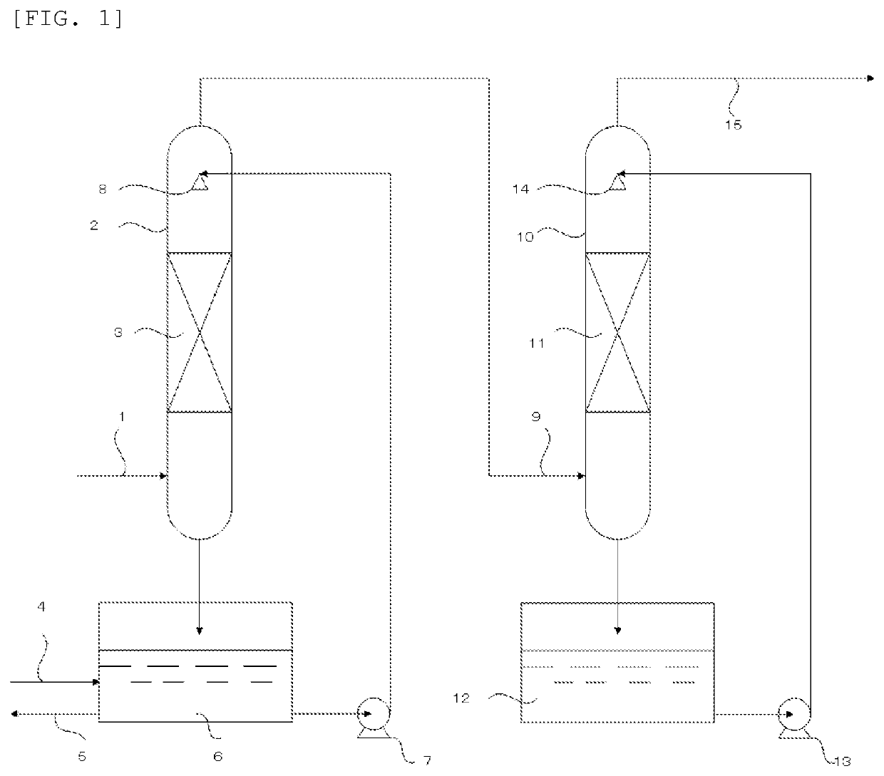
[0059]Treatment of an exhaust gas was performed by using an apparatus equipped with a first absorption column (2) having a diameter of 500 mm in which cascade mini-rings as a filling material were filled at a filling height of 4 m in a filling layer 1(3) and a second absorption column (10) having a diameter of 500 mm in which cascade mini-rings as a filling material were filled at a filling height of 4 m in a filling layer 2 (11). FIG. 1 depicts a schematic diagram.

[0060]At the first step performed on the first absorption column (2) side, water was introduced into a circulation liquid tank 1 (6), and circulated at 4 m3 / hr. The amount of water introduced and the amount of the circulation liquid discharged were adjusted such that an HF concentration in the circulation liquid tank 1(6) was 3% by mass.

[0061]At the second step performed on the second absorption column (10) side, a basic aqueous solution including a reducing agent (pH at charging: 13.5) prepared so that KOH as the base ha...

example 2

[0065]Exhaust gas treatment was performed in the same manner as Example 1 except that, in Example 1, the F2 concentration in the exhaust gas to be treated was 40% by volume. The gas component discharged from the first absorption column (2) and introduced into the second absorption column (10) was a gas including 20,000 ppm by volume of F2, 1,300 ppm by volume of HF, and 42,000 ppm by volume of OF2.

[0066]Table 1 has listed concentrations of respective fluorine-based gas elements in the treated gas discharged from the treated gas discharging pipe (15) and amounts of consumption of chemical solution (the basic aqueous solution including a reducing agent) in the second step. Neither F2 nor HF was detected from the treated gas, and 1 ppm by volume of OF2 was detected therefrom. In addition, the amounts of the chemical solution consumed in the second absorption column (10) were 6.7 kg / hr for KOH as the base and 18 kg / hr for K2SO3 as the reducing agent.

example 3

[0067]Exhaust gas treatment was performed in the same manner as Example 1 except that, in Example 1, sodium thiosulfate (Na2S2O3) was used in place of potassium sulfite (K2SO3), as the reducing agent in the chemical solution (the basic aqueous solution including a reducing agent) used at the second step, and the concentration of Na2S2O3 was set to 3% by mass.

[0068]Table 1 has listed concentrations of respective fluorine-based gas elements in the treated gas discharged from the treated gas discharging pipe (15) and amounts of consumption of chemical solution (the basic aqueous solution including a reducing agent) in the second step. Neither F2 nor OF2 nor HF was detected from the treated gas. Additionally, the amounts of the chemical solution consumed in the second absorption column (10) were 0.7 kg / hr for KOH as the base and 1.9 kg / hr for Na2S2O3 as the reducing agent.


PUM

PropertyMeasurementUnit
temperatureaaaaaaaaaa
diameteraaaaaaaaaa
diameteraaaaaaaaaa

Abstract

A method for treating a fluorine element-containing exhaust gas including a first step of contacting the fluorine element-containing exhaust gas with water and a second step of contacting a gas component discharged from the first step with a basic aqueous solution including a reducing agent.

Description

TECHNICAL FIELD[0001]The present invention relates to a method for treating a fluorine element-containing exhaust gas that treats the fluorine element-containing exhaust gas and discharges a treated gas containing reduced amounts of fluorine-based gases such as fluorine gas (F2), oxygen difluoride (OF2), and hydrogen fluoride (HF).BACKGROUND ART[0002]Fluorine compounds are used in large amounts in a variety of fields, for purposes such as manufacturing of semiconductors, liquid crystals, and the like, raw materials of chemical products and polymer materials, or surface modifications.[0003]Particularly, in manufacturing processes for semiconductors, liquid crystals, and the like, fluorine-based gases such as F2, NF3, SiF4, COF2, SF6, and fluorocarbons (such as CF4, C2F6, and C4F6) have been conventionally used as gases for etching and cleaning. In processes using fluorine-based gases, gases derived from the used fluorine-based gases or fluorine element-containing gases produced by re...

Claims


Application Information

Patent Timeline
Patent Type & Authority Applications(United States)
IPC IPC(8): B01D53/68B01D53/14B01D53/78B01D53/75
CPCB01D53/68B01D53/1493B01D53/1406B01D53/1456B01D2257/2047B01D53/75B01D2252/103B01D2257/2027B01D53/78B01D53/14B01D2252/2056B01D53/79B01D2251/20
Inventor MURAKAWA, MINAKOSANO, TOMOMITODA, ASAKO
Owner SHOWA DENKO KK
Why Eureka
Try Eureka