Imaging lens and imaging apparatus

a technology of imaging apparatus and lens barrel, which is applied in the field of imaging lens, can solve the problems of insufficiently coping with the recent demands for a decrease in size and a reduction in the ratio of the total length of the lens, an increase in or an increase in the manufacture cost, so as to achieve convenient operation, reduce manufacturing costs, and reduce the size of the lens barrel

Active Publication Date: 2017-08-24
FUJIFILM CORP
View PDF3 Cites 3 Cited by
  • Summary
  • Abstract
  • Description
  • Claims
  • Application Information

AI Technical Summary

Benefits of technology

[0031]According to the present invention, the lens system consists of, in order from the object side, the first lens group having a positive power, the diaphragm, the second lens group having a positive power, and the third lens group. In the lens system, during focusing from an infinite distance object to a close-range object, elements ranging from the first lens group to the second lens group integrally move to the object side, and the third lens group remains stationary. Thereby, configurations of the respective lens groups are appropriately set such that the lens groups further satisfy predetermined conditional expressions. Thus, it is possible to provide a front-focus-type imaging lens, which has a small size and has a favorable optical performance so as to be capable of simplifying an apparatus configuration, and an imaging apparatus comprising this imaging lens.

Problems solved by technology

Lens systems of Examples 1 to 5 of JP2013-218015A does not sufficiently cope with recent demands for a decrease in size and an increase in ratio of the total length of the lens to the image sensor size in a state where the infinite distance object is in focus.
Thus, a mechanism for moving the lens groups becomes complicated, and this leads to an increase in size of a lens barrel or an increase in manufacture costs.

Method used


Image

  • Imaging lens and imaging apparatus
  • Imaging lens and imaging apparatus
  • Imaging lens and imaging apparatus

Examples


example 1

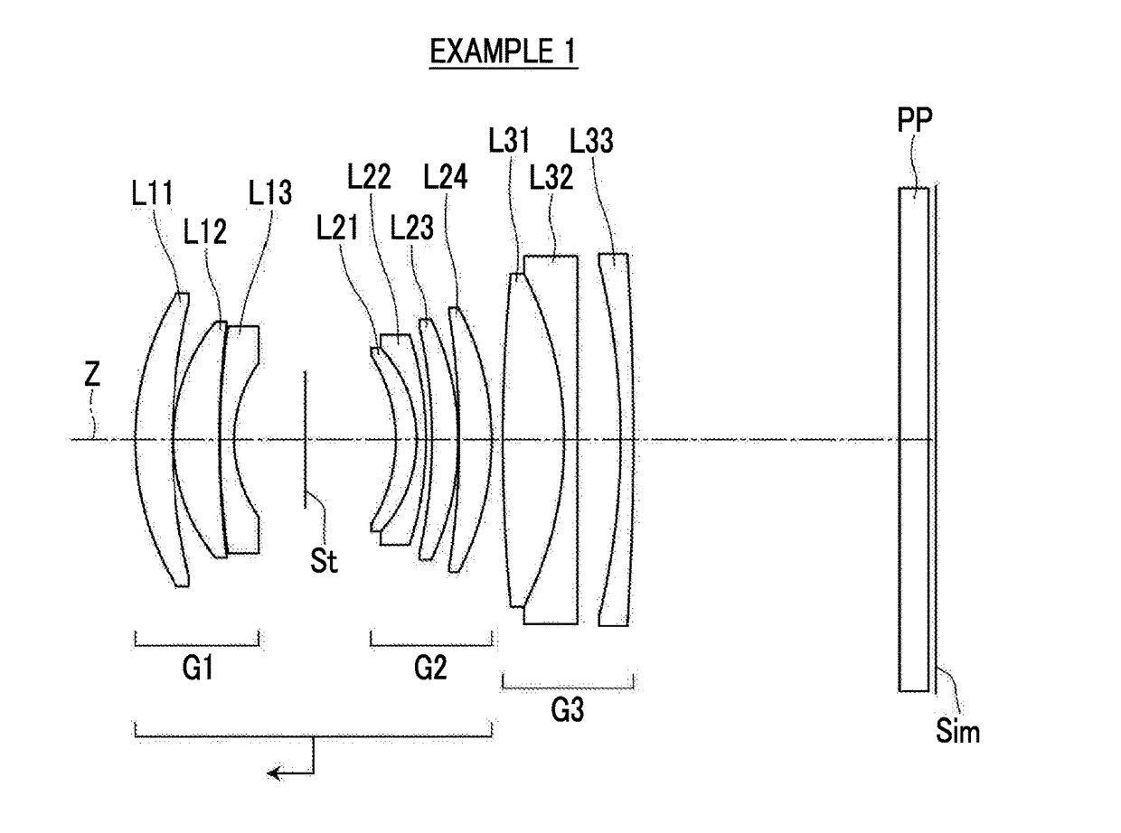
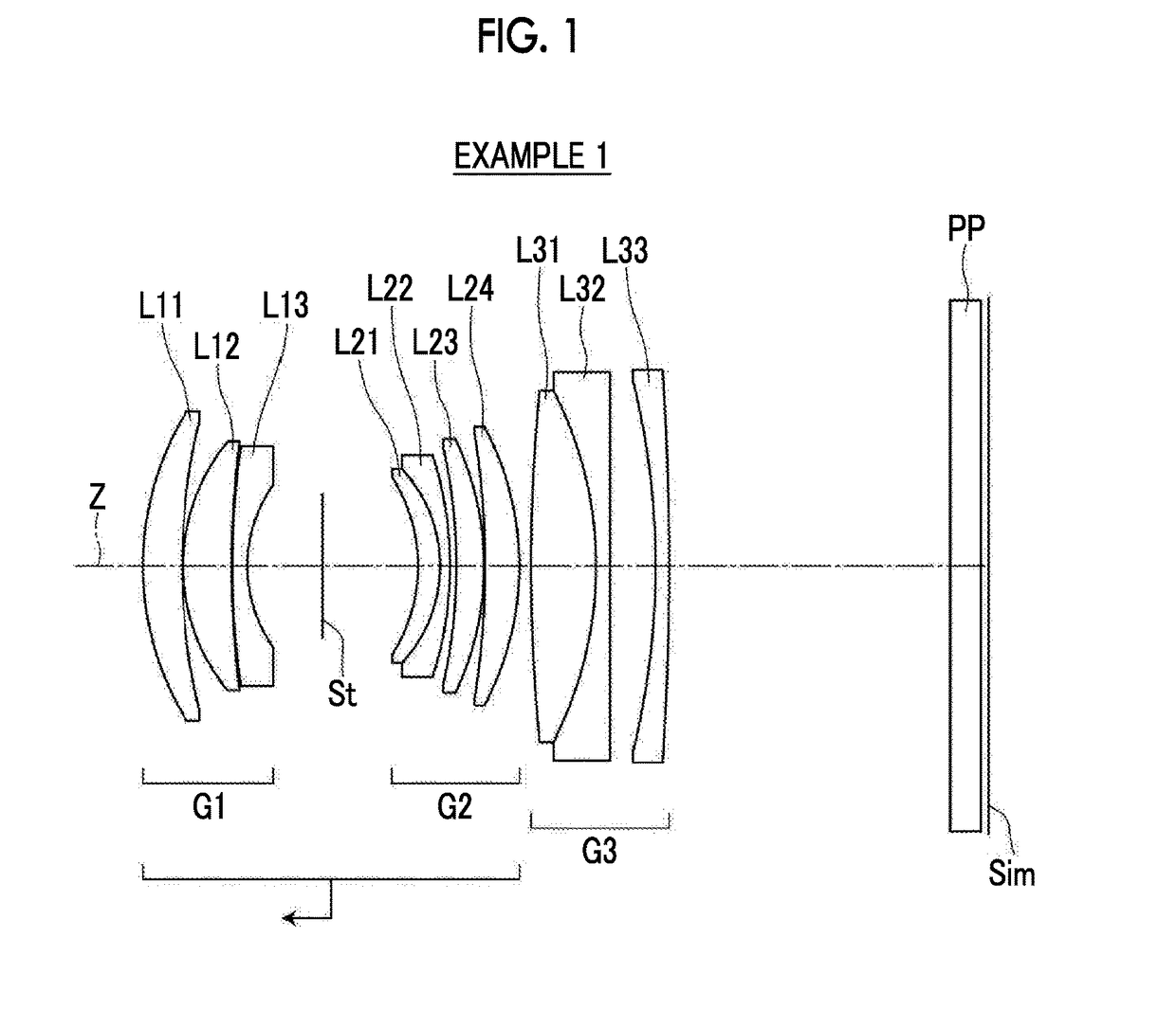
[0091]The cross-sectional view of the imaging lens of Example 1 is shown in FIG. 1, the configuration and the method thereof shown in the drawing is as described above. Thus, repeated description is partially omitted herein. As a group configuration, the imaging lens of Example 1 includes, in order from the object side, three groups, that is, a first lens group G1 that has a positive refractive power, an aperture diaphragm St, a second lens group G2 that has a positive refractive power, and a third lens group G3 that has a positive refractive power group. During focusing from an infinite distance object to a close-range object, the first lens group G1, the aperture diaphragm St, and the second lens group G2 integrally move toward the object side, and the third lens group G3 remains stationary with respect to the image plane Sim. The first lens group G1 includes three lenses, that is, lenses L11 to L13 in order from the object side, the second lens group G2 includes four lenses, that...

example 2

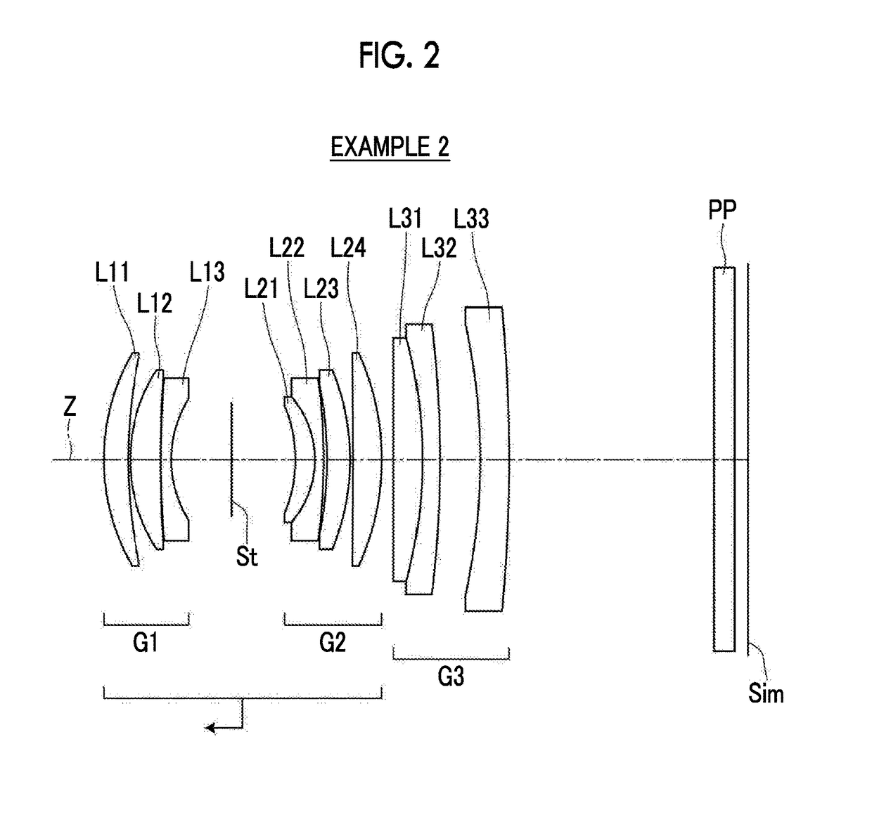
[0098]FIG. 2 is a cross-sectional view of an imaging lens of Example 2. The group configuration of the imaging lens of Example 2 is the same as that of Example 1. The first lens group G1 includes three lenses, that is, lenses L11 to L13 in order from the object side, the second lens group G2 includes four lenses, that is, lenses L21 to L24 in order from the object side, and the third lens group G3 includes three lenses, that is, lenses L31 to L33 in order from the object side. Table 3 shows basic lens data of the imaging lens of Example 2, Table 4 shows specification, and FIG. 10 shows aberration diagrams thereof.

TABLE 3Example 2SiRiDiNdjνdj131.81823.58001.9537532.32272.83690.2900324.37194.49001.5163364.144178.24140.03905147.59141.53001.6989530.13617.14298.81007(St)∞9.29008−20.90762.85001.5928268.629−14.23221.27001.5927035.3110−93.33450.500011−55.84893.36002.0010029.1312−35.32950.420013−959.48774.21001.7432049.3414−38.52001.680015∞4.20001.7291654.6816−71.18662.53001.5927035.3117−167...

example 3

[0099]FIG. 3 is a cross-sectional view of an imaging lens of Example 3. The group configuration of the imaging lens of Example 3 is the same as that of Example 1. The first lens group G1 includes three lenses, that is, lenses L11 to L13 in order from the object side, the second lens group G2 includes four lenses, that is, lenses L21 to L24 in order from the object side, and the third lens group G3 includes three lenses, that is, lenses L31 to L33 in order from the object side. Table 5 shows basic lens data of the imaging lens of Example 3, Table 6 shows specification, and FIG. 11 shows aberration diagrams thereof.

TABLE 5Example 3SiRiDiNdjνdj125.99594.58001.8348142.72267.98100.2000324.41384.31001.5163364.144149.70730.03905140.77950.84001.6398034.47615.882910.16177(St)∞7.50008−18.13942.94001.5928268.629−13.15021.27001.5927035.3110−66.66700.270011−54.19783.76002.0010029.1312−35.04040.420013−180.87734.00001.7432049.3414−38.71831.260015∞3.78001.7291654.6816−105.35462.53001.6889331.071720...


PUM


Abstract

The imaging lens consists of, in order from the object side, a first lens group G1 having a positive power, a diaphragm, a second lens group G2 having a positive power, and a third lens group G3. Each of the lens groups includes three or more lenses. A positive lens is disposed on a most object side in the first lens group G1, and a meniscus lens, which is concave toward the object side, is disposed to be closest to the object side in the second lens group G2. During focusing from an infinite distance object to a close-range object, elements ranging from the first lens group G1 to the second lens group G2 integrally move toward the object side, and the third lens group G3 remains stationary. The imaging lens satisfies a conditional expression about a radius of curvature of an air lens of the first lens group G1.

Description

CROSS-REFERENCE TO RELATED APPLICATIONS[0001]The present application claims priority under 35 U.S.C. §119 to Japanese Patent Application No. 2016-028609, filed on Feb. 18, 2016. Each of the above application(s) is hereby expressly incorporated by reference, in its entirety, into the present application.BACKGROUND OF THE INVENTION[0002]1. Field of the Invention[0003]The present invention relates to an imaging lens, which is appropriate for a digital camera, a video camera, and / or the like, and an imaging apparatus which comprises the imaging lens.[0004]2. Description of the Related Art[0005]In the related art, as imaging lenses that can be used in cameras in the field mentioned above, for example, imaging lenses proposed in the following JP2013-019994A and JP2013-218015A. JP2013-019994A describes a lens system that includes in order from the object side: a first lens group that has a positive refractive power; a second lens group that has a negative refractive power; a third lens gro...

Claims


Application Information

Patent Timeline
Patent Type & Authority Applications(United States)
IPC IPC(8): G02B13/00G02B9/12G02B7/10
CPCG02B13/001G02B9/12G02B7/10G02B15/163G02B9/64G02B13/16
Inventor KONDO, MASATO
Owner FUJIFILM CORP
Why Eureka
Try Eureka