2D/3D Registration

a technology of 2d/3d and registration, applied in the field of 2d/3d registration, can solve the problems of prejudiced motion estimation and unnecessary computational operations, and achieve the effects of less sensitiveness, improved resolution, and increased area

Active Publication Date: 2017-08-24
SIEMENS HEALTHCARE GMBH
View PDF0 Cites 13 Cited by
  • Summary
  • Abstract
  • Description
  • Claims
  • Application Information

AI Technical Summary

Benefits of technology

[0031]In a particularly preferred embodiment of the method it may be provided that the gradient x-ray image and the gradient comparison image are initially determined in a coarser resolution with larger image elements than the x-ray image, wherein the determination of the motion parameters and the correction of the test transformation are repeated successively in order at least to provide a better resolution, in particular up to the resolution of the x-ray image. As has already been indicated, the image-based analysis conducted in order to find contour points is by its nature particularly suited to such a multiple resolution scheme, by means of which consideration is initially given to larger image elements which combine smaller image elements of the size of the image elements of the x-ray image. This has several advantages. For one thing, it is possible in this way to increase the size of the area in which movements relative to the three-dimensional image dataset are captured, since the algorithm initially reacts less sensitively. The robustness of the procedure is therefore increased significantly. A type of “pyramid representation” is therefore given, where, for example, resolutions may be increased from 64×64 image elements, through 128×128 and 256×256 image elements, to 512×512 image elements. In this way, the accuracy of the determination of the motion parameters, and consequently the registration transformation, is improved incrementally.
[0032]If a plurality of image elements of the size of the image elements of the x-ray image are to be combined, a way must be found in respect of the gradients to specify a useful gradient for the larger image element. It can be provided with particular advantage in th

Problems solved by technology

In the dynamic registration approach described therein, the selection of the starting points (and consequently contour points) was namely non-trivial for a variety of reasons, on the one hand because the projected contour points typically cover the regions of two-dimensional interest in a redundant manner, wi

Method used


Image

  • 2D/3D Registration
  • 2D/3D Registration
  • 2D/3D Registration

Examples


Embodiment Construction

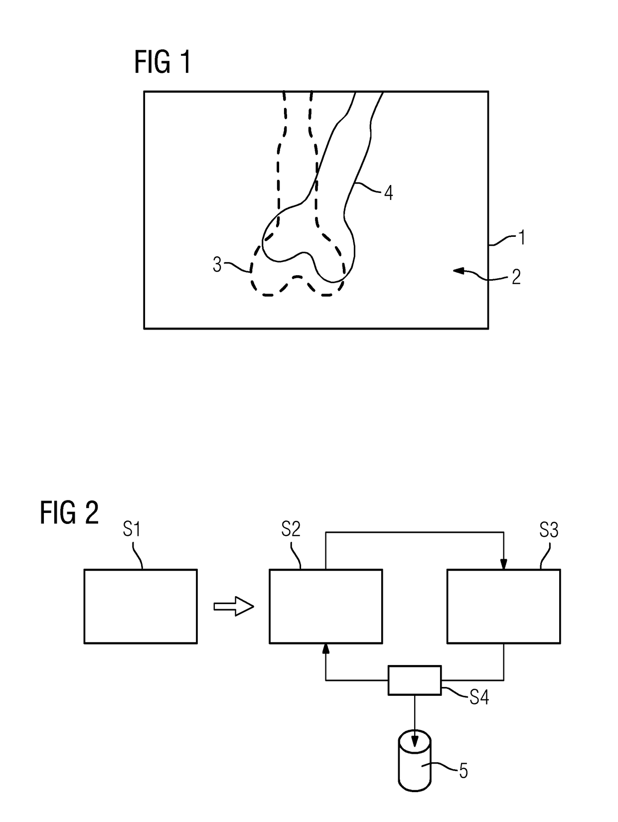
[0070]FIG. 1 shows by way of example and in a schematic representation an overlay image 1 from a three-dimensional image dataset and an x-ray image, wherein the x-ray image 2 forms the basis onto which the information 3 of the three-dimensional image dataset is superimposed as an overlay. A shadow-like, low-resolution anatomical structure 4, in this case a bone, is discernible in the x-ray image 2. The information 3 relating to the same anatomical structure 4, the overlaying being brought about using a coarse initial transformation, hence a coarse 2D / 3D registration, was superimposed from the three-dimensional image dataset. It is apparent that the anatomical structure according to the information 3 is slightly skewed and translated relative to the visible anatomical structure 4 of the x-ray image 2. The below-described exemplary embodiment of the method now aims to determine a registration transformation that leads to an accurate overlaying of said anatomical structures, hence to a...


PUM


Abstract

A method includes, following specification of an initial transformation as a test transformation that is to be optimized, determining a 2D gradient x-ray image and a 3D gradient dataset of the image dataset, carrying out, for each image element of the gradient comparison image, a check for selection as a contour point, and determining an environment best corresponding to a local environment of the contour point and extending around a comparison point in the gradient x-ray image for all contour points in the at least one gradient comparison image. Local 2D displacement information is determined by comparing the contour points with the associated comparison points, and motion parameters of a 3D motion model describing a movement of the target region between the acquisition of the image dataset and the x-ray image are determined from the displacement information and a registration transformation describing the registration.

Description

[0001]This application claims the benefit of DE 10 2016 202 512.0, filed on Feb. 18, 2016, which is hereby incorporated by reference in its entirety.BACKGROUND[0002]The present embodiments relate to registering a three-dimensional image dataset of a target region of a patient with a two-dimensional x-ray image of the target region recorded in an acquisition geometry.[0003]In many problematic medical situations, whether it be in diagnostics or when performing minimally invasive interventions in particular, both three-dimensional image data in the form of an image dataset, for example a computed tomography or magnetic resonance dataset, and two-dimensional fluoroscopic images, i.e. typically x-ray images, are available for the target region of interest of the patient. In such situations, it is desirable to be able to carry out a joint evaluation of both the three-dimensional image dataset and the two-dimensional x-ray image of the target region, in particular in the form of a fusion i...

Claims


Application Information

Patent Timeline
IPC IPC(8): G06T7/37G06T7/246G06T7/269G06T7/207A61B6/00G06T7/38G06T7/00G06T19/00G06T11/00G06T7/32G06T7/564
CPCG06T7/37G06T2207/30008G06T7/248G06T7/269G06T7/207G06T7/564G06T7/38G06T7/0016G06T19/003G06T11/006G06T11/005A61B6/5211A61B6/5264G06T2200/04G06T2200/28G06T2207/10121G06T2207/10081G06T2207/10088G06T2207/10028G06T2207/20016G06T2207/20221G06T7/32G06T2207/10116G06T7/33A61B6/032A61B6/487A61B6/5229A61B6/5235
Inventor SCHAFFERT, ROMANWANG, JIANBORSDORF, ANJA
Owner SIEMENS HEALTHCARE GMBH
Why Eureka
Try Eureka