
Power storage device and power storage system

a technology of power storage device and power storage system, which is applied in the direction of secondary cell servicing/maintenance, sustainable manufacturing/processing, batteries, etc., can solve the problem of reducing the maximum capacity of the battery, and achieve the effect of reducing the capacity

Active Publication Date: 2017-08-24
SEMICON ENERGY LAB CO LTD
View PDF14 Cites 9 Cited by
  • Summary
  • Abstract
  • Description
  • Claims
  • Application Information

AI Technical Summary

Benefits of technology

The present invention provides a power storage system or a power storage device that can restore reduced capacity, through the use of a capacity restoration device outside of the battery. Additionally, the power storage system includes an ion conducting portion that is connected to the battery without any space at joints, providing flexibility in the system. The power storage device can also have a pump and an air vent to facilitate the movement of ions and the evacuation of air. The invention also allows for the use of a novel power storage system or power storage device.

Problems solved by technology

However, the maximum capacity with respect to the battery capacity is reduced in the lithium-ion secondary battery including the third electrode which is disclosed in Patent Document 1 because the third electrode does not contribute to formation of charge and discharge capacity during normal operation of the battery.

Method used


Image

  • Power storage device and power storage system
  • Power storage device and power storage system
  • Power storage device and power storage system

Examples


embodiment 1

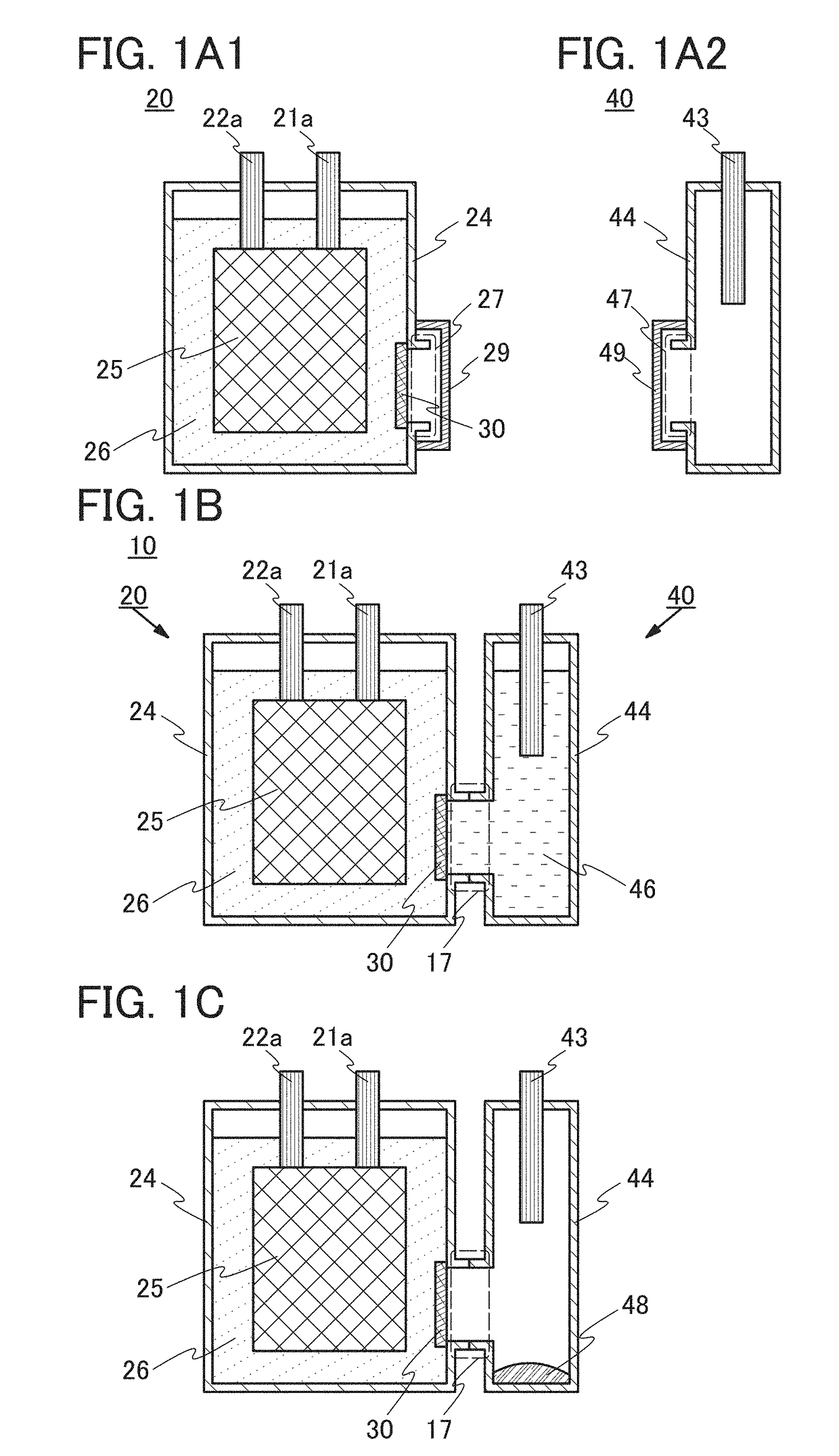
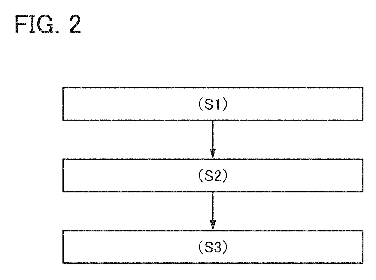
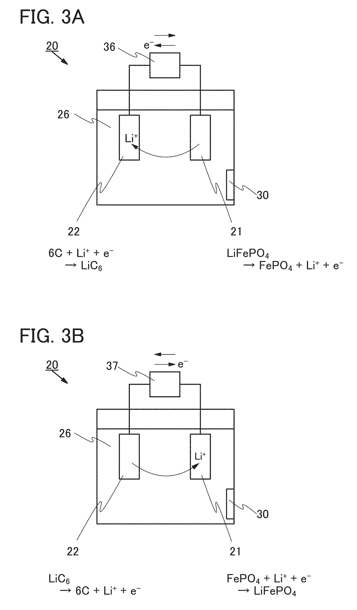
[0060]In this embodiment, a structure of a power storage system of one embodiment of the present invention will be described with reference to FIGS. 1A1, 1A2, 1B, and 1C, FIG. 2, FIGS. 3A and 3B, FIGS. 4A and 4B, and FIG. 5.

[0061]FIG. 1A1 and FIG. 1A2 are schematic views of a power storage device 20 and a capacity restoration device 40, respectively. A power storage system 10 of one embodiment of the present invention includes the power storage device 20 and the capacity restoration device 40.

[Structure of Power Storage Device]

[0062]The power storage device 20 includes an exterior body 24, a component group 25, an electrolyte solution 26, and a carrier ion permeable film 30 (see FIG. 1A1). The component group 25 includes a first electrode 21 (not illustrated), a second electrode 22 (not illustrated), and a plurality of members, such as a separator, for charging and discharging the power storage device. Note that specific structure examples of the first electrode 21, the second elect...

embodiment 2

[0104]In this embodiment, a structure of a power storage system of one embodiment of the present invention will be described with reference to FIGS. 6A to 6C and FIGS. 7A and 7B.

[0105]FIG. 6A is a schematic diagram of a power storage system 60 at the time of capacity restoration treatment. The power storage system 60 includes the power storage device 20 and the capacity restoration device 40. The description of Embodiment 1 can be referred to for the structures of the power storage device 20 and the capacity restoration device 40.

[0106]The power storage system 60 includes an ion conducting portion 61, the charger 36, a cable 63a, and a cable 63b. The ion conducting portion 61 has a function of carrying carrier ions while being filled with the electrolyte solution 46.

[0107]The ion conducting portion 61 is connected to the opening 27 provided in the exterior body of the power storage device 20 and the opening 47 provided in the exterior body of the capacity restoration device 40 witho...

embodiment 3

[0120]In this embodiment, a structure of a power storage system of one embodiment of the present invention will be described with reference to FIG. 8.

[0121]The power storage system of one embodiment of the present invention can perform capacity restoration treatment on two or more power storage devices at the same time in the following manner. Thus, the capacity restoration treatment can be performed efficiently.

[0122]FIG. 8 is a schematic top view of a power storage system 70. The power storage system 70 includes a power storage device 20A, a power storage device 20B, and the capacity restoration device 40. The description of the power storage device 20 and the description of the capacity restoration device 40 in Embodiment 1 can be referred to for the structures of the power storage device 20A and the power storage device 20B and the structure of the capacity restoration device 40, respectively. In addition, the description of Embodiment 2 can be referred to for the components of ...


PUM

PropertyMeasurementUnit
thicknessaaaaaaaaaa
average diameteraaaaaaaaaa
specific surface areaaaaaaaaaaa

Abstract

A power storage system or a power storage device that can restore reduced capacity is provided. The power storage device includes a first exterior body, a first electrode, a second electrode, a first electrolyte solution, and a carrier ion permeable film. The first electrode, the second electrode, and the first electrolyte solution are covered with the first exterior body. The first electrode and the second electrode are in contact with the first electrolyte solution. The first electrolyte solution includes carrier ions. A first opening is provided in the first exterior body. The carrier ion permeable film is provided to be in contact with the first electrolyte solution and so as to block the first opening without any space. The carrier ion permeable film is configured to be impermeable to water and air but permeable to the carrier ions.

Description

BACKGROUND OF THE INVENTION[0001]1. Field of the Invention[0002]One embodiment of the present invention relates to a power storage device. Another embodiment of the present invention relates to a power storage system. Another embodiment of the present invention relates to a method for restoring capacity of a power storage device of one embodiment of the present invention.[0003]Note that one embodiment of the present invention is not limited to the above technical field. The technical field of one embodiment of the invention disclosed in this specification and the like relates to an object, a method, or a manufacturing method. Furthermore, one embodiment of the present invention relates to a process, a machine, manufacture, or a composition of matter. Specific examples of the technical field of one embodiment of the present invention disclosed in this specification include a semiconductor device, a display device, a power storage device, a memory device, a method for driving any of t...

Claims


Application Information

Patent Timeline
Patent Type & Authority Applications(United States)
IPC IPC(8): H01M10/44H02J7/00H01M2/16H01M10/0525H01M10/46H01M50/409H01M50/443H01M50/627H01M50/77
CPCH01M10/44H01M10/0525H01M10/46H01M2220/20H02J7/0042H01M2220/30H01M2/164H01M10/4214H01M50/409H01M50/443H01M50/627H01M10/052H01M10/058H01M10/0583H01M10/0585H01M10/4242H01M10/425Y02E60/10H01M50/30H01M50/77Y02P70/50
Inventor MOMO, JUNPEI
Owner SEMICON ENERGY LAB CO LTD
Learn More