Stencil Frames

a technology of stencil frames and stents, applied in the direction of conductive pattern formation, manufacturing tools, solventing apparatus, etc., can solve the problems of non-contact situations, components or short circuits shifting, and producing unwanted contact points, so as to achieve higher pre-tension and high tension

Active Publication Date: 2017-08-24
FRY S METALS INC
View PDF2 Cites 0 Cited by
  • Summary
  • Abstract
  • Description
  • Claims
  • Application Information

AI Technical Summary

Benefits of technology

[0007]The proposed solution is based on the realisation that a stencil frame can be decomposed into corner elements and edge elements that can be moved relative to one other and pre-tensioned by springs. The corner elements and / or the edge elements may optionally be created by rectangular and patterned extruded profiles much more cheaply than pneumatically-released frames.
[0041]Preferably, each spacer element may be connected to the reception profile in which it is received. For example, by use of a perpendicular fixing pin or screw that is fixed to the edge element forming the reception profile. Advantageously, this may help keep the spacer element in a central position.

Problems solved by technology

Non-uniform tensioning of the stencil foil, as well as any protrusions from the assembly board, can cause a solder paste volume different from the desired volume being applied to the assembly board which can result in shifting of components or short circuits between component leads which may be designed only with small pitch separations.
Any level difference on the assembly board, for example, conductive paths covered with solder mask or self-adhesive markers, can also lead to non-contact situations.
Two typical soldering defects which may occur are ‘solder bridges’ between component leads producing an unwanted contact point and ‘skips’ where electric and / or mechanical contact between the component and the assembly board is not adequately formed.
As these must be stored through the full lifetime of the circuits they take up huge volumes in electronics manufacturing facilities.
However, the adjustment operation is burdensome and slow.
Despite unquestioned utility of those systems a significant drawback is that they need large numbers of complex shaped, typically metal, components with a requirement for tight manufacturing tolerances leading to a manufacturing cost which is high and the resulting frames may be prone to defects.

Method used


Image

  • Stencil Frames
  • Stencil Frames
  • Stencil Frames

Examples


Embodiment Construction

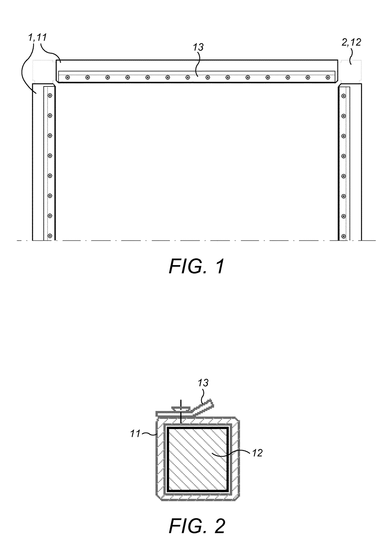
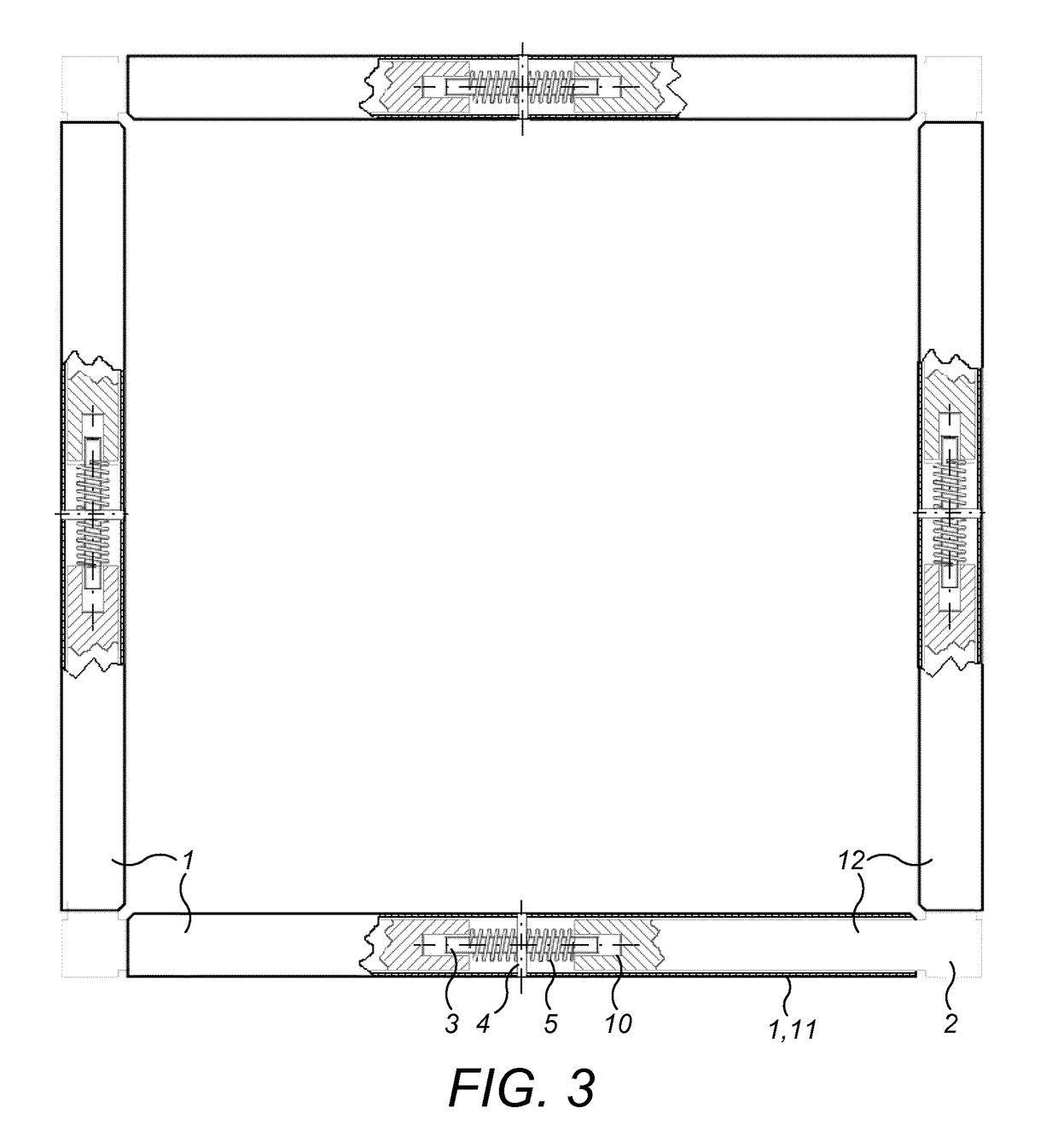
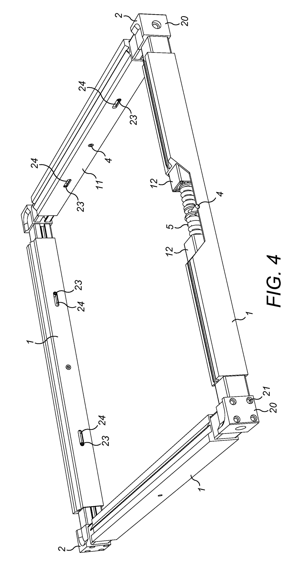
[0064]Looking at FIG. 1 we can recognise the general frame structure where the fastening element 13 is actually a bent metal strip assembled with screws and which can anchor the edge element of a stencil foil. Instead of the fastening element 13 the frame can be anchored to the stencil foil by other known methods like edge clamping or pins, screws or splines perpendicular to edge element 1 and that can attach to openings made alongside the edge of the stencil foil. The fastening element 13 can furthermore be a shoulder perpendicular to the plane of the stencil that is also bound to the edge elements 1. The tensioning frame tensions the stencil foil so, that the corner elements 2 connect with the edge elements 1 in an axial direction of the corner elements 2 and can move relatively to each-other. Between the aforementioned parts tensioning devices are mounted that strive to separate from each-other the opposed edge elements 1. The corner elements 2 define the relative angle of the ed...


PUM

PropertyMeasurementUnit
weightaaaaaaaaaa
sizeaaaaaaaaaa
weightaaaaaaaaaa

Abstract

Stencil frames for tensioning stencils of an angular shape are provided. The stencil frame comprises corner elements (2), edge elements (1), fastening elements (13) and tensioning devices with a tensioning device being associated with each edge element (1). The corner elements (2) each have two, mutually perpendicular, guiding profiles (12) which joined at an intersection of their axes and the edge elements (1) each have a uniaxial reception profile (11). Each reception profile (11) is connectable to two guiding profiles (12) by loose fit. Each tensioning device has at least one elastic element (5) and connects between two neighbouring corner elements (2). A line of force exerted by each tensioning device is parallel to the axis of its corresponding reception profile (11).

Description

TECHNICAL FIELD[0001]This disclosure relates to stencil frames for uniform tensioning of stencil foils. The stencil frames may allow a stencil foil to be releasably mounted to the stencil frame. The stencil frames may be used for solder paste application onto a circuit substrate during surface-mount device (SMD) circuit production.BACKGROUND[0002]The most widespread bonding technology used in the electronics industry is the so-called reflow soldering. The appearance of solder in this technology is solder paste that is a solvent suspension of solder alloy and flux. In mass production solder paste is first applied to the surface of the assembly board (usually woven glass fabric reinforced epoxy resin) or other circuit substrate through a thin metal fixture commonly referred to as a stencil or stencil foil. The stencil foil is a machined metal tool, typically in the form of a sheet, with openings (apertures) on it matching the contact surfaces of the assembly board. During printing a c...

Claims


Application Information

Patent Timeline
Patent Type & Authority Applications(United States)
IPC IPC(8): H05K3/12B23K1/00B23K3/06H05K3/34
CPCH05K3/1225H05K3/3484B23K3/0638B23K3/0623B23K1/0016B41F15/0881B41F15/36B41P2215/12H05K3/3485
Inventor KASZLI, PETER
Owner FRY S METALS INC
Why Eureka
Try Eureka