

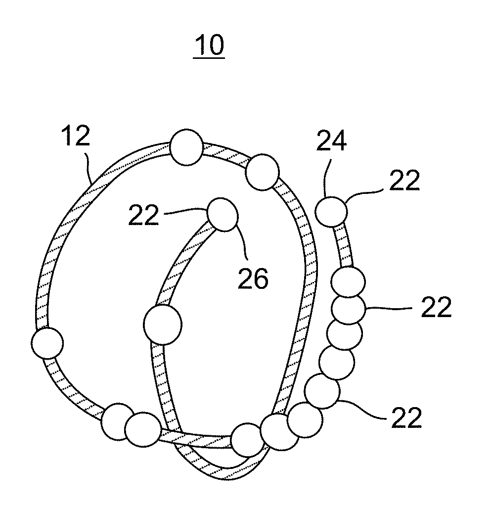
Device positionable in the uterine cavity
a technology of uterine cavity and device, which is applied in the direction of contraceptive devices, medical devices, female contraceptives, etc., can solve the problems of increased menstrual bleeding or cramps, side effects, and increased risk of ovarian cysts, and achieve maximum stability
- Summary
- Abstract
- Description
- Claims
- Application Information
AI Technical Summary
Benefits of technology
Problems solved by technology
Method used
Image

Examples
example 1
[0098]A clinical study employing an IUD device based on the teachings of US20110271963 was initiated in January of 2014. The study included fifty female subjects, 1 post-abortive, 39 with heavy menses, and 44 nulliparous.
[0099]Three month follow-up data for 29 of the 51 test subjects was obtained and analyzed. Ten cases of expulsions were reported. There were no reports of pregnancies, perforation or malposition. Of the 29 monitored subjects, 19 / 29 reported being “very happy” and 9 / 29 “somewhat happy”.
[0100]While the study has no comparative arm and offers a limited basis for analysis it was observed that there could potentially be an expulsion issue. In order to address this issue, the TUB was modified as described herein to improve the performance of the device in-situ. Design changes included increasing the frame diameter by 30% from 10 mm to 13 mm and increasing the rigidity of the frame by increasing the wire diameter by ˜30% from 0.335 to 0.432 to further reduce malleability w...
example 2
Multi-Center Study
[0101]A multi-center study was conducted in order to test the expulsion and pregnancy rate as well as the number of malposition incidents of the present device. The number of patients varied between 15 and 220 and included women aged 15 to 42 who met specific inclusion and exclusion criteria and who were in need of long acting reversible contraception.
[0102]Table 1 below summarizes the findings.
TABLE 1clinical data collected from four studies using the present deviceStudyExpulsionPregnancyGroupInsertionsExpulsionsratePregnanciesrateMalpositionA15 00000B5010 20%000C220 52.2%10.45%0D200 8* 5%000Total485234.7%1 0.2%0*Six of eight expulsions seen with the same physician, caused by what appears to be a non-advised insertion technique of withdrawing the tube 1.5 cm before deploying the device. Corrective training action has been taken.
[0103]Overall data appears to meet or improve on published adverse event rates. Expulsion rate in study group B is related to poor candid...
PUM
 Abstract
Description
Claims
Application Information